16_ installation & connection
installation & connection
`
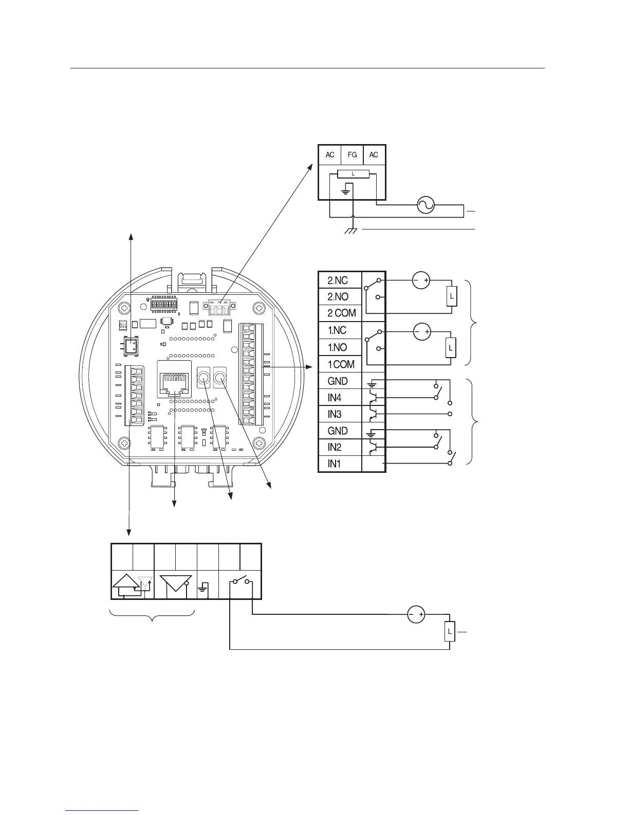
Camera Wiring Interface Board
For the camera wiring, please refer to the picture below.
2N.C
2N.0
COM2
1N.C
1N.0
COM1
GND
IN4
IN3
GND
IN2
IN1
Alarm
IN1 IN2 GND IN3 IN4 GND 1C0M 1.N0 1.NC 2C0M 2.N0 2.NC
AXICOM
IMO3
5VDC
AXICOM
IMO3
5VDC
AXICOM
IMO3
5VDC
Video Out
AUDIO_OUTAUDIO_IN
Power
AC 22~26V
Alarm2 ONAlarm1 ON
D+ D- TXD+
TXD-
GND
A.COM
A.NO
AUDIO_OUTAUDIO_IN
AXICOM
IMO3
5VDC
Alarm2 ON
1143Н
AXICOM
IMO3
5VDC
Alarm1 ON
1143Н
AXICOM
IMO3
5VDC
1143Н
IN1 IN2 GND IN3 IN4 GND 1C0M 1.N0 1.NC 2C0M 2.N0 2.NC
ON DIP
D+ D- TXD+
TXD-
GND
A.COM
A.NO
D+ D- TXD+ TXD- GND
A.COM
A.NO
Video
Output
Communications and AUX
Refer to Control Signal
Connection Diagram
Power Supply
AC24V 6A
Alarm
ETHERNET
Audio IN
Alarm output
Alarm Input
Power Input
AUX Output
Ground
Audio OUT
 Loading...