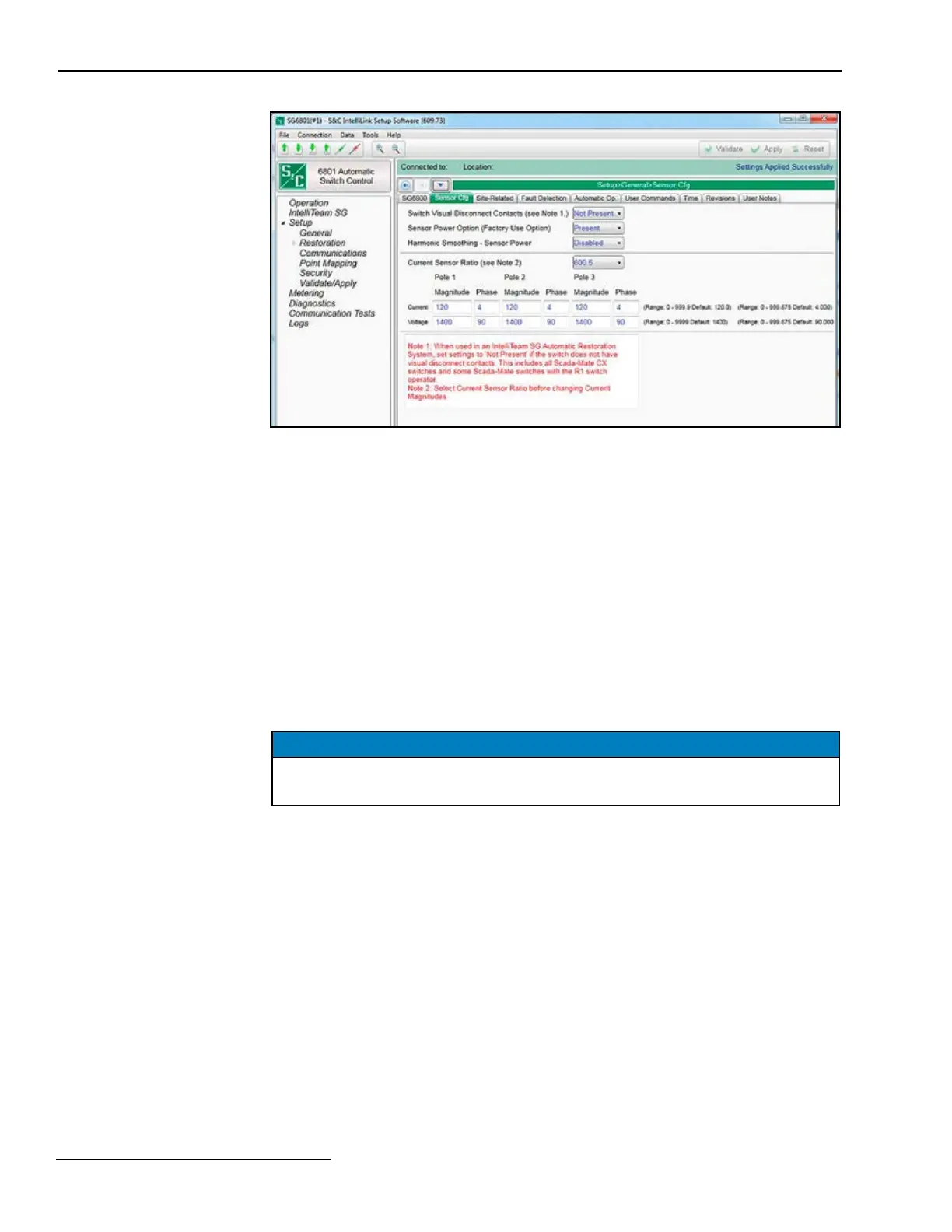
Figure 8. The Setup>General>Sensor Configuration screen (6801 switch control shown).
This screen allows entering calibration data for S&C Scada-Mate® Switching Systems;
automated Omni-Rupter® Switches; and PME, PMH, or Vista Underground Distribution
Switchgear sensors. See Figure 8. The switch control uses this data to calibrate sensor
input to the voltage and current amplitude accuracy specied for S&C sensors.
Current (Magnitude/Phase) & Voltage (Magnitude/Phase) on
Poles 1, 2, and 3
S&C sensors are factory-calibrated. The sensor ratios are stamped on each sensor and
are provided in the information sheet shipped with the switch. The number of sensors
must be selected before entering calibration factors. Ratios must be entered on this
screen to obtain accurate voltage and current measurements. Each eld already has the
approximate default value to reduce the number of keystrokes needed to enter data. The
switch control ignores values for any pole not specied in the Voltage Sensors Present
setting on the Setup>General>Site-Related screen. Store the calibration data sheet in
the control-door pocket for future reference.
NOTICE
Ratios must be entered for phase B when phases A, B, and C are measured. The
phase B ratios are used to adjust all voltage scales for 15-, 25-, or 35-kV systems.
This screen may also include the following fields:
Switch Visual Disconnect Contacts (only applicable to SG6801, SG6801E33, and
SG6802DO software)
All Scada-Mate Switches equipped with R2 switch operators have visual-disconnect
contacts. Visual-disconnect contacts are optional with the R1 switch operator. When
the switch has visual-disconnect contacts, select the Present option for this setpoint.
When the visual-disconnect contacts are open, the ERROR DETECTED indicator on the
faceplate is on, and the Logs>Historic Log screen indicates a Not Ready condition and a
Disconnect Active condition. These conditions clear when the switch visual disconnect
is manually closed. Scada-Mate CX™ Switching Systems do not have visual-disconnect
contacts. When the switch does not have visual disconnect contacts, select the Not
Present option (default) for this setpoint.
Note: When used in an IntelliTeam SG Automatic Restoration System, select the Not
Present setpoint when the switch does not have visual disconnect contacts. This includes
all Scada-Mate CX switches and some Scada-Mate switches with the R1 switch operator.
Switch Control Setup
Sensor Configuration
22 S&C Instruction Sheet 1045-530
 Loading...

