Switch Control Setup
Pct DeadBand
This is the deadband range expressed as a percentage of the previously reported analog
input data. If the analog input data associated with this point exceed the range in either
a positive or negative direction, the information will be included in the next event report.
Specify the N/A option to turn off deadband reporting as a percentage of the previously
reported analog input data.
Fixed DeadBand
This is the deadband range expressed as a xed value relative to the previously reported
analog input data. If the analog input data associated with this point exceed the range in
either a positive or negative direction, the information will be included in the next event
report. Specify the N/A option to turn off deadband reporting as a xed value relative
to the previously reported analog input data.
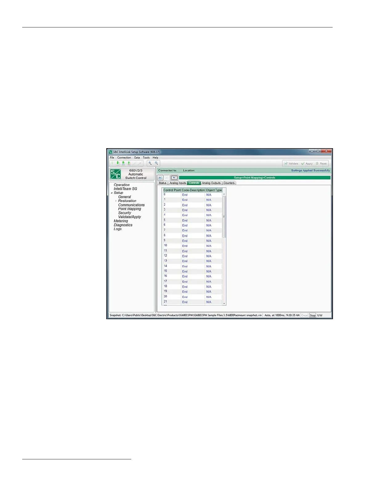
Figure 40. The Setup>Point Mapping>Control Points screen.
The screen shown in Figure 40 contains conguration parameters for Control point
mapping. Map these points to make them available in the SCADA system.
Control Point
This is the point number the SCADA system will use when operating the Control point.
Code-Description
These are the point codes representing specic Control points that may be assigned to
individual SCADA point numbers. Setting a Code-Description point code to the “End”
setting denes the end of the congured points list and the maximum number of Control
points that can be returned.
Object Type
This species the type of control code the SCADA master will use in the control relay
output block request. Specify “Breaker” for a Trip/Close operation, “Latch” for a Latched
On/Off operation, “Pulse” for a momentary control output, or “N/A” if the control point will
DNP Control Point
Mapping
82 S&C Instruction Sheet 1045-530
 Loading...

