-45-
1. Voltage adjustment
Equipment Digital voltmeter
Connections + K6D(2)
- chassis ground
Adjustment:
Adjust the voltage of K6D to 6.35± 0.05V DC with the VR652.
2. AV Video signal adjustments
Equipment Oscilloscope
Input mode AV
Input signal 16 step gray scale signal
Picture condition Normal
Set the image to "Service mode."
2-1. AV Green Video adjustment
Connections : + TP211 or TP5182 / - chassis ground.
Adjust each item for below values with the Volume + and - buttons.
Group No. Adjustment part. Adjustment or adjustment value.
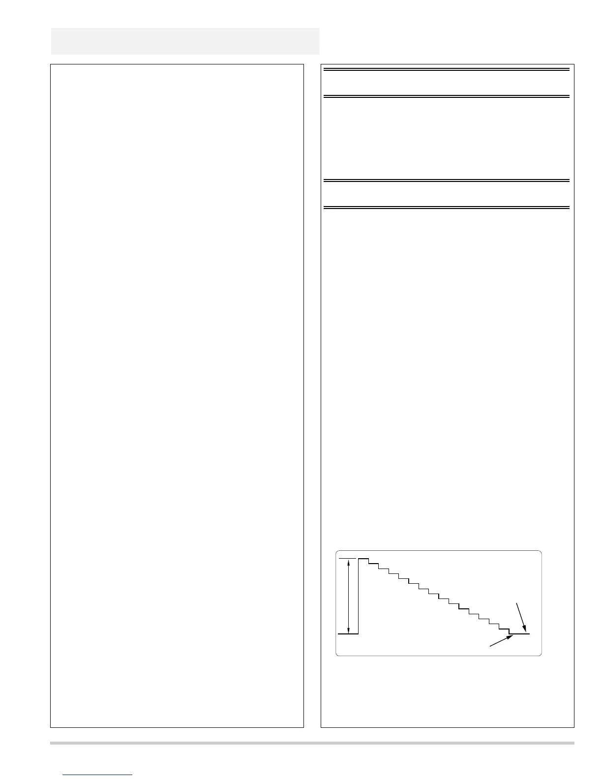
1010- 0 Amplitude-A in a figure. 0.7± 0.05Vp-p
1010- 1 Pedestal level and black level. Make it the same level.
2-2. AV Red Video adjustment
Connections : + TP201 or TP5181 / - chassis ground.
Adjust each item for below values with the Volume + and - buttons.
Group No.
Adjustment part. Adjustment or adjustment value.
1010- 2 Amplitude-A in a figure. 0.7± 0.05Vp-p
1010- 3 Pedestal level and black level. Make it the same level.
2-3. AV Blue Video adjustment
Connections : + TP221 or TP5183 / - chassis ground.
Adjust each item for below values with the Volume + and - buttons.
Group No.
Adjustment part. Adjustment or adjustment value.
1010- 4 Amplitude-A in a figure. 0.7± 0.05Vp-p
1010- 5 Pedestal level and black level. Make it the same level.
Note :
■ The following adjustment is the adjustment item for Assembly power.
The test point exists on the Assembly power.
1. Voltage adjustment.
■ The following adjustments are the adjustment item for Terminal
board-AV. The adjustment data is stored to Terminal board-AV
(IC2143). The test points exist on the Terminal board-AV and the
Assembly main.
2. AV Video signal adjustments.
3. 3DNR-PLL Lock check.
4. AV Color and Tint adjustments.
■ The following adjustment is the adjustment item for Assembly sub
power. But the adjustment data is stored to Assembly main (IC1811 and
IC871). The test points exist on the Assembly PBS fan-net, the
Assembly EXH fan-net and the Assembly sub-power.
5. Fans driving voltage adjustments.
■ The following adjustments are the adjustment item for Assembly main.
The adjustment data is stored to Assembly main (IC1811 and IC871). The
test points exist on the Assembly main.
6. Video center DC adjustments.
7. PSIG signal adjustments.
8. PC contrast adjustments.
9. AV contrast adjustments.
10. Panel driving signal adjustments -AV.
11. Panel driving signal adjustments -PC.
12. Flicker reduction.
13. White balance adjustments.
14. Unevenness color correction.
Location of test points can see it on
"PWB parts location diagrams."
■ Electrical adjustments
 Loading...