monitoring parameters in sequence. Other parameters display can be set by FE.08~FE.09, for details see parameter codes
table FE.08~FE.09); or without pressing , but set tens place of FE.12 as 1 (alternate display of main and secondary
parameters), and the stopped state monitoring parameters will display circularly every other second automatically; also
enter monitoring menu by pressing , and check each monitoring parameter by , and .
3.5 Malfunction Alarm Display
The VFD enters into malfunction alarm display status upon detecting failure signal and display failure code (as shown in
Fig 3-4); Press to check relative parameters of stopped inveter; to check failure information, press and enter
into program mode to check D group parameter. After troubleshooting, conduct fault resetting by key on the
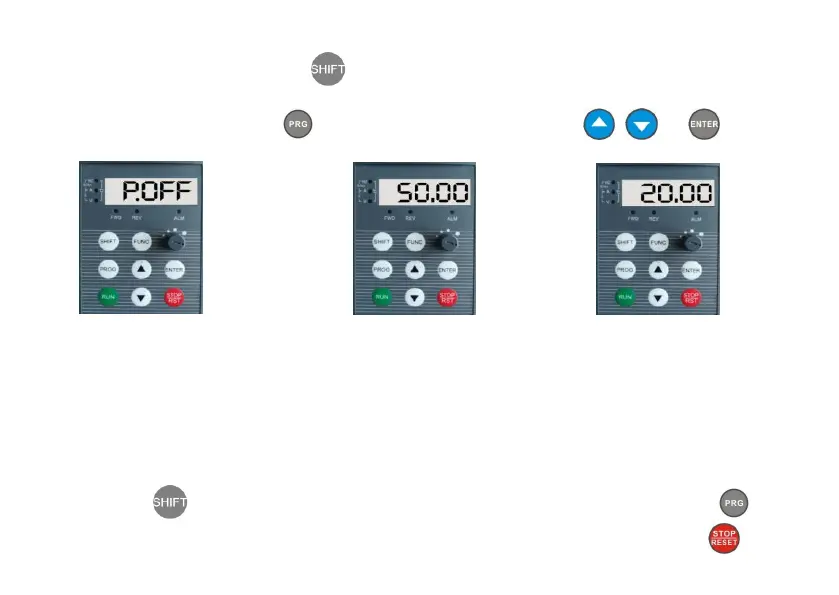
Fig 3-1 Power-on Parameter Display
Initialization Display “P.OFF”
Fig 3-2 Stop Status Parameter Display
Display Set Frequency “50.00”
Fig 3-3 Run Status Parameter Display
Display Current Output Frequency “20.00”
 Loading...