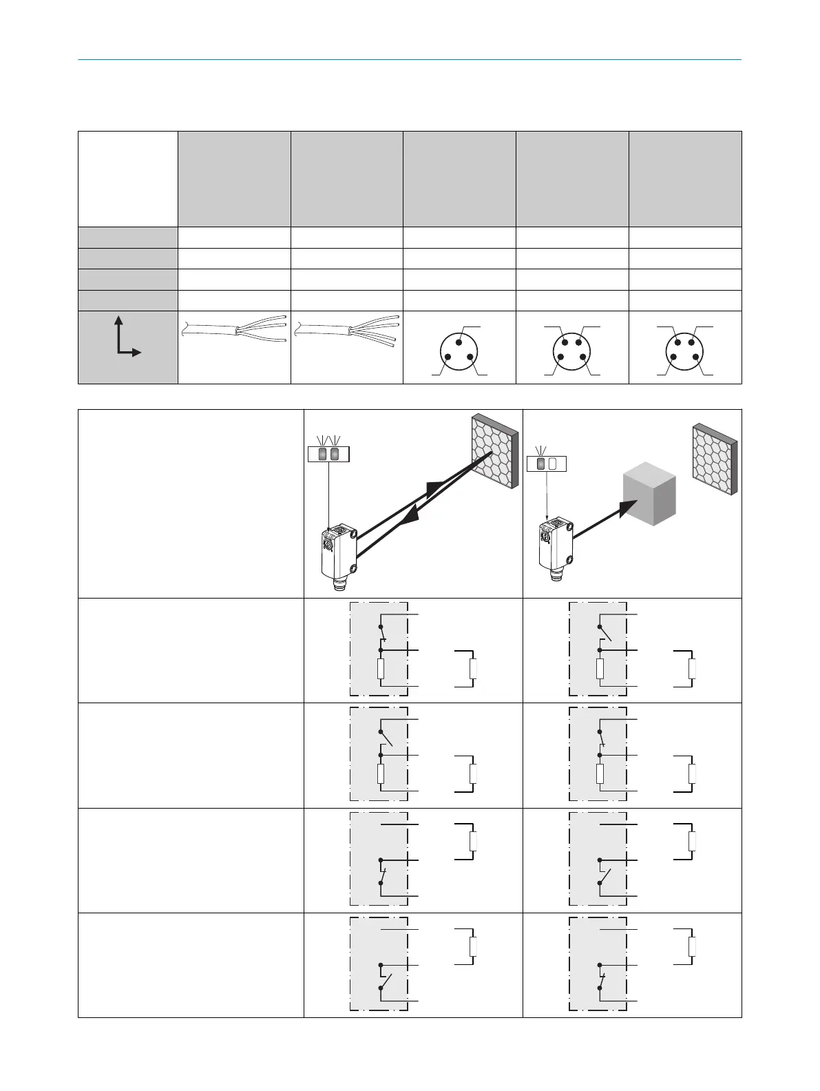
Connection and Output detail:
T
able 1: DC
GL6L -P1xxx
-N1xxx
-E2xxx
-F2xxx
-P3xxx
-N3xxx
-P5xxx
-N5xxx
-P4xxx
-N4xxx
-P6xxx
-N6xxx
-P7xxx
-N7xxx
-E4xxx
-F4xxx
-E6xxx
-F6xxx
-E7xxx
-F7xxx
1 = BN + (L+) + (L+) + (L+) + (L+) + (L+)
2 = WH -
Q
- n. c.
Q
3 = BU - (M) - (M) - (M) - (M) - (M)
4 = BK Q Q Q Q Q
0.205 mm
2
/
A
WG24
0.205 mm
2
/
A
WG24
Table 2: Output Operation
GL6L
-Pxxxx = Q out
put
-Nxxxx = Q output
-Fxxxx = Q + Q output
-Exxxx = Q + Q output
-Px1xx
-Px2xx
-Px5xx
-Px6xx
L.ON
, PNP: Q (≤ 100 mA)
-Px1xx
-Px2xx
-Px3xx
-Px4xx
D.ON
, PNP: Q (≤ 100 mA)
-Nx1xx
-Nx2xx
-Nx5xx
-Nx6xx
L.ON
, NPN Open Collector Q (≤ 100 mA)
+ (L+)
Q
‒
(M)
+ (L+)
Q
‒ (M)
Load
-Nx1xx
-Nx2xx
-Nx3xx
-Nx4xx
D.ON
, NPN Open Collector Q (≤ 100 mA)
+ (L+)
Q
‒
(M)
+ (L+)
Q
‒ (M)
Load
ELECTRICAL INSTALLATION 6
8025389 / 24.06.2020 | SICK
Subject to change without notice
7

 Loading...