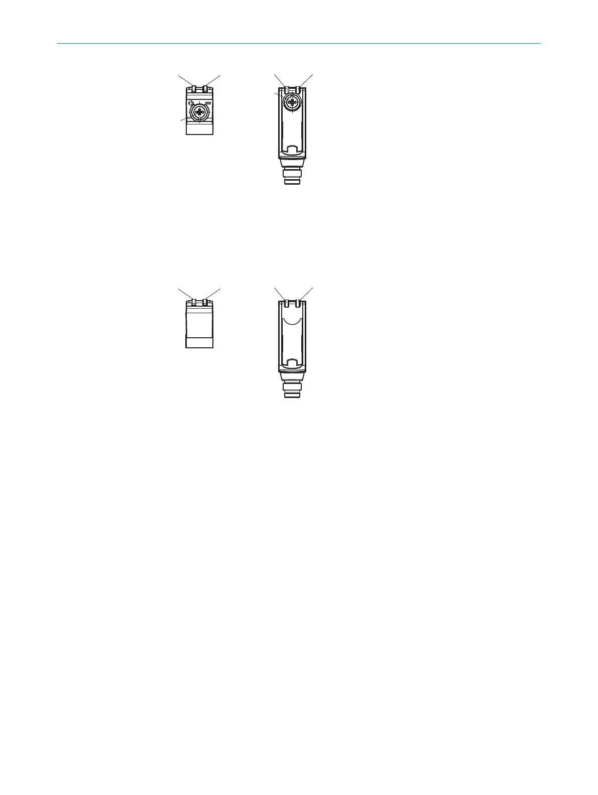
1
Potentiometer: sensitivity adjustment
2
Yellow LED indicator: Switching output
3
LED indicator green: supply voltage active
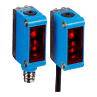
GL6L-xxx3x
Sensor whic
h it is not possible to set: The sensor is adjusted and ready for operation.
5 Mounting
Mount the sensor and the reflector using suitable mounting brackets (see the SICK
r
ange of accessories). Align the sensor and reflector with each other.
6 Electrical installation
The sensors must be connected in a voltage-free state (U
V
= 0 V
). The following informa‐
tion must be observed depending on the connection type:
– Plug connection: pin assignment
– Cable: wire color
Only apply voltage/switch on the voltage supply (U
V
> 0 V) once all electrical connec‐
tions have been established.
Explanation of connection terminology:
BN = Brown
WH = White
BU = Blue
BK = Black
n. c. = no connection
Q = switching output 1
Q = switching output 2
L+ = supply voltage (Uv)
M = common
L.ON = light operate
D.ON = dark operate
4 O
PERATING AND STATUS INDICATORS
6
8025389 / 24.06.2020 | SICK
Subject to change without notice

 Loading...