INTRODUCTION
_________________________________________________________________________________________________________
1-3
SIG-QG-17-05 DECEMBER 2017
Version No.: A
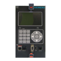
Table 1-1 Display Module Controls, Indicators, Connectors, and Display Descriptions
2 ½ x 4 inch OLED Color Display
5-key membrane navigational cluster
CPU data stream indicators
TX LED (Green) RX LED (Yellow)
Communications data stream indicators
TX LED (Green) RX LED (Yellow)
SEAR data stream indicators
TX LED (Green) RX LED (Yellow)
Echelon
®
LAN data indicators
TX LED (Green) RX LED (Yellow)
Ethernet Power indicator LED (Green)
Ethernet 1 data indicators (embedded in connector)
Data:TX LED (Green) RX LED (Yellow)
Ethernet 2 data indicators (embedded in connector)
TX LED (Green) RX LED (Yellow)
RJ-45 powered connector (See note)
DB-9, Female Serial connector, RS-232
1
Ethernet 1 and Ethernet 2 ports are not available on the GCP4000, therefore these ports on
the Display module are not useable.
The Ethernet 1 powered connector is designed specifically for
Siemens Ethernet Spread Spectrum Radios and may not power other
Power-Over-Ethernet (POE) devices.
 Loading...


