OPERATION
_________________________________________________________________________________________________________
3-6
SIG-QG-17-05 DECEMBER 2017
Version No.: A
The Ethernet 1 powered
connector is designed specifically for
Siemens Ethernet Spread Spectrum Radios and may not power other
Power-Over-Ethernet (POE) devices.
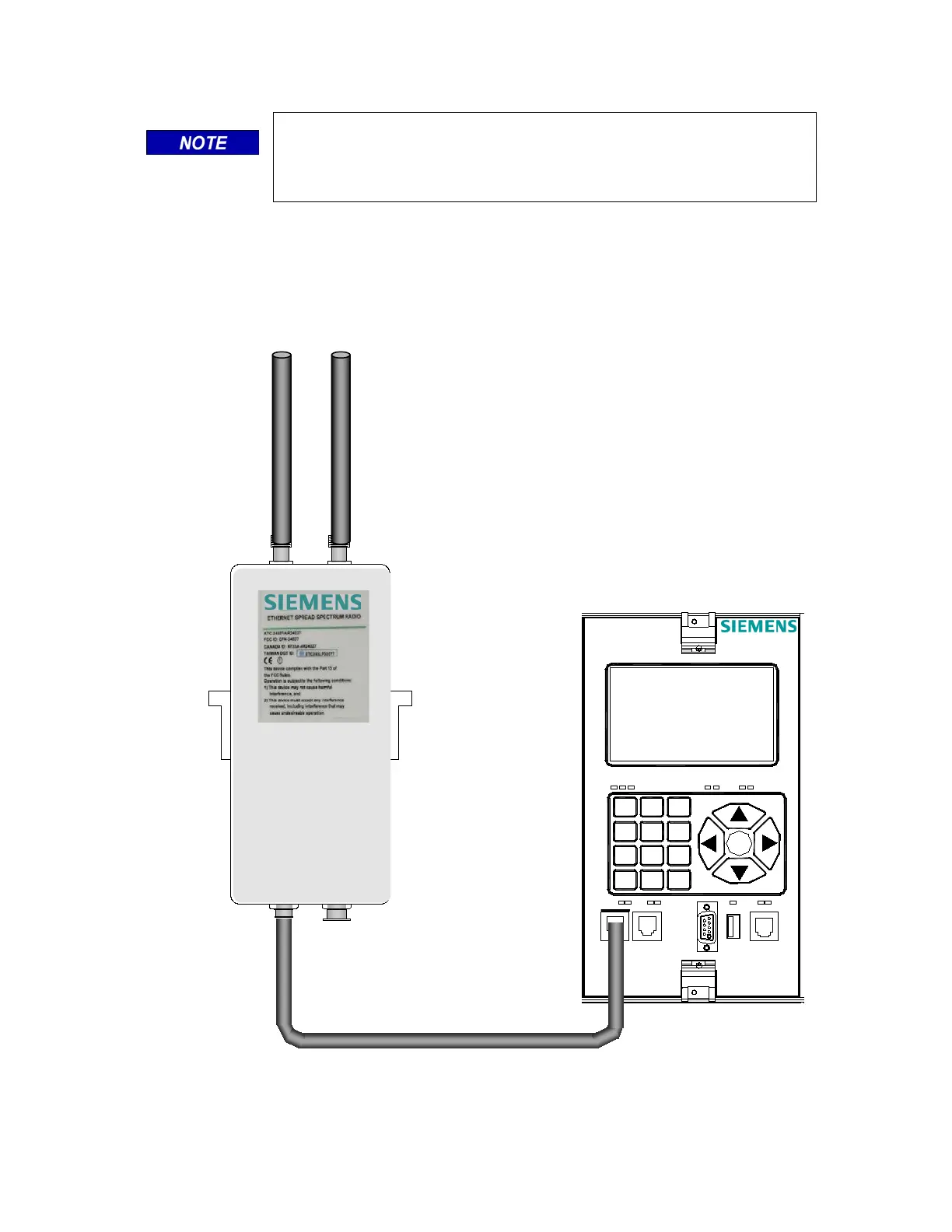
3.4.1 Display Module to Ethernet 1 Port Power-Over-Ethernet (POE) Device Connection
An example of an Ethernet 1 port Power-Over-Ethernet device connection using the Siemens
Ethernet Spread Spectrum Radio is shown in Figure 3-7. Connection from the GCP Display to
the Ethernet powered device is usually connected using an Ethernet cable that is provided with
the Ethernet device. Refer to the Ethernet device instructions for further information.
Figure 3-7 Display Module to Ethernet Power-Over-Ethernet Device Connection
(M9)
1
Symbol
2
ABC
3
DEF
4
GHI
5
JKL
6
MNO
7
PQRS
8
TUV
9
WXYZ
HELP
0
Space
BACK
ENTER
USB
LAPTOP
DIAG
CPU
SEAR
TX RX
POWER
TX RX
DISPLAY
Module
A80485-2
COM
TX RX
ECHELON
ETHERNET 2ETHERNET 1
ETH
PWR
 Loading...


