V1.20 Page 15 of 48 ICM MP CCQ GRM
A55/C55_Hitachi Company Confidential © Copyright Siemens AG 04/03
4.4 Receiver
4.4.1 Receiver: EGSM900/1800 –Filter to Demodulator
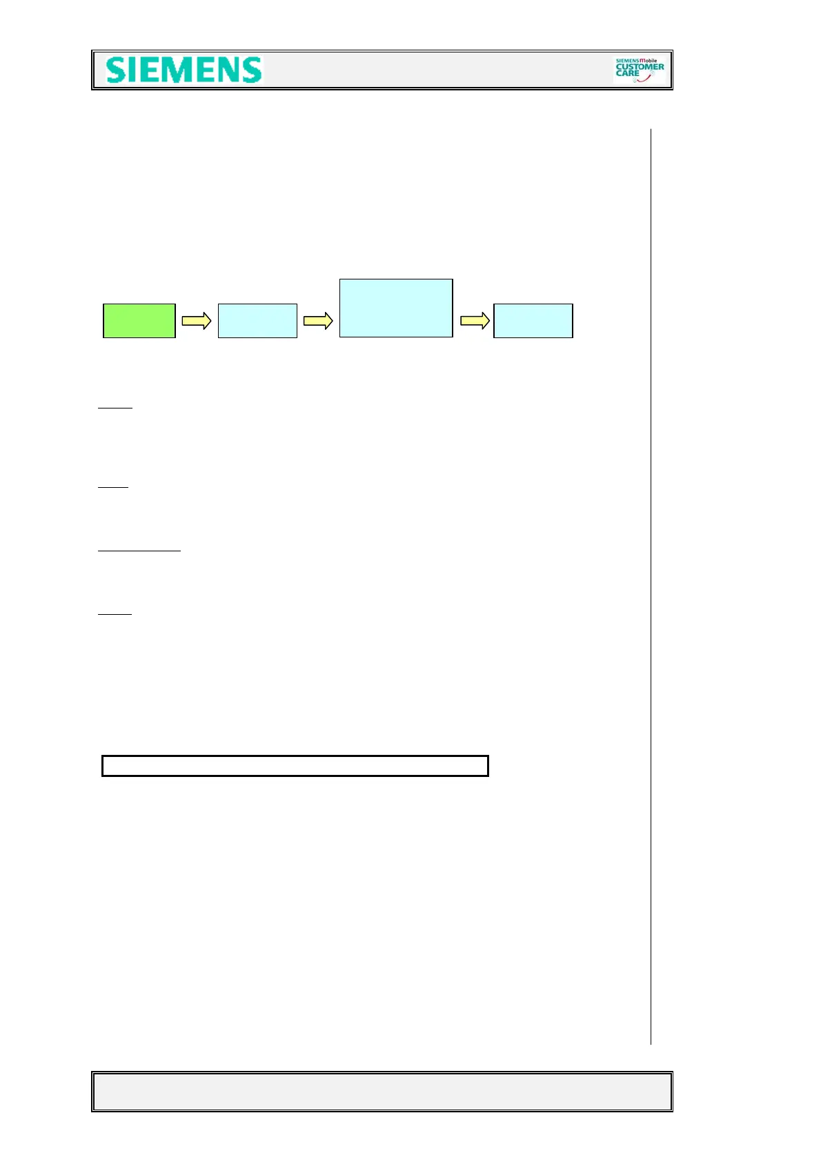
From the antenna switch, up to the demodulator the received signal passes the
following blocks to get the demodulated baseband signals for the EGOLD+:
Z880 Bright Bright Bright
Filter:
The EGSM900 and GSM 1800 filters are located inside the frontend module.
The Filter are centred to a frequency of 942,5MHz for EEGSM900 and 1847,5MHz for
GSM1800. The symmetrical filter output is matched via LC-Combinations to the LNA
input of the BRIGHT (D800)
LNA:
The 2 LNA´s (EGSM900/1800) are located inside the BRIGHT and are able to
perform an amplification of ~ 20dB. The LNA can be switched in HIGH (On) and LOW
(Off) mode and is controlled by the Bright depending on EGOLD+ information.
Demodulator:
The Bright IC performs a direct demodulation of the received GSM
signals. To do so the LO1 is required. The channel depending LO1 frequencies for
1800MHz band are divided by 2 and by 4 for 900MHz band, Bright internally.
PGC:
After demodulation the “I” and “Q” signals are amplified by the PGC-Amplifier
the “I” and the “Q” path are amplified independently from each other. The performance
of this PGC is 80dB (-26 up to 54dB), switchable in steps of 2dB. The control is
realised through the EGOLD+ signals (RFDATA; RFCLK; RFSTR.
(RF Control J15, J16,
J17
). After passing a Bright internal switch (necessary because of the double using of
RX and TX lines), the signals are ready for further processing through the EGAIM
(part of the EGOLD+) The post-switched logic measures the level of the demodulated
baseband signal an regulates the level to a defined value by varying the PGA-
Amplification and switching the appropriate LNA gains
The required voltage VCC_SYN is provided by the ASIC D361
Filter LNA
PGC
De-
modulator
 Loading...