V1.20 Page 7 of 48 ICM MP CCQ GRM
A55/C55_Hitachi Company Confidential © Copyright Siemens AG 04/03
4.2 Frequency generation
4.2.1 Synthesizer: The discrete VCXO (26MHz)
The A55/C55 mobile is using a reference frequency of 26MHz for the Hitachi chip set.
The generation of the 26MHz signal is done via a discrete “Colpitts” VCXO. This
oscillator consists mainly of:
A 26MHz crystal Z950
An oscillator switch V950
A capacity diode V951
TP (test point) of the 26MHz signal is the TP 1501
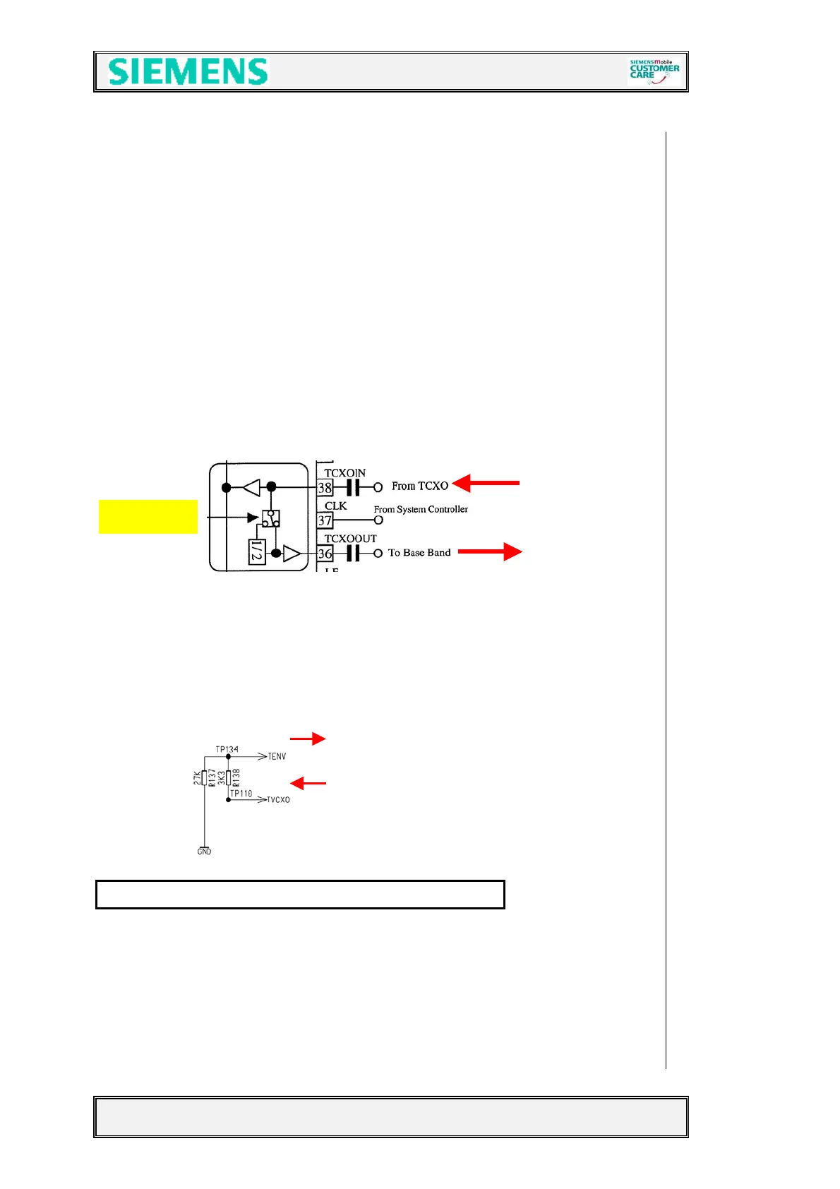
The oscillator output signal 26MHz_RF is directly connected to the BRIGHT IC (pin
38) to be used as reference frequency inside the Bright (PLL). The signal leaves the
Bright IC as BB_SIN26M at pin 36 to be further used from
the EGOLD+ (D100
(functional T3)).
To compensate frequency drifts (e.g. caused by temperature) the oscillator frequency
is controlled by the (AFC) signal, generated through the internal EGOLD+ (D100
(functional U5)) PLL via the capacity diode V951. Reference for the “EGOLD-PLL” is the
base station frequency. To compensate a temperature caused frequency drift, the
temperature-depending resistor R959 is placed near the VCXO to measure the
temperature. The measurement result TVCXO is reported to the EGOLD+
(Analog
Interface P3)
via R138 as the signal TENV.
The required voltage VCC_SYN is provided by the ASCI D361
Bright 4
 Loading...