V1.20 Page 6 of 48 ICM MP CCQ GRM
A55/C55_Hitachi Company Confidential © Copyright Siemens AG 04/03
CC2
8
CC
SYN
4 Radio Part
The radio part of the A55/C55, is using a Hitachi and an Infineon RF chip-set. This
manual covers the Hitachi chip-set. For Infineon there is an additional manual
available.
The radio part is designed for Dual Band operation, covering EEGSM900 as well as
GSM 1800 frequencies, and can be divided into 4 Blocks.
-Power supply for RF-Part
-Transmitter
-Receiver
-Synthesizer,
The RF-Part has it´s own power supply realised by a voltage regulator which is
located
inside the ASIC. The voltages for the logic part are generated by the Power-Supply
ASIC too.
The transmitter part converts the I/Q base band signals supplied by the logic
(EGOLD+) into RF-signals with characteristics as defined in the GSM
recommendation (www.etsi.org
) After amplification by a power Amplifier the signal is
radiated via the internal or external antenna.
The receiver part converts the received GMSK signal supplied by the antenna into IQ
base band signals which are further processed by the logic (EGOLD+).
The synthesizer generates the required frequencies for the transmitter and receiver. A
26MHz oscillator is acting as a reference frequency.
Restrictions:
The mobile phone can never transmit and receive in both bands simultaneously. Only
the monitor time slot can be selected independently of the frequency band.
Transmitter and receiver can of course never operated simultaneously.
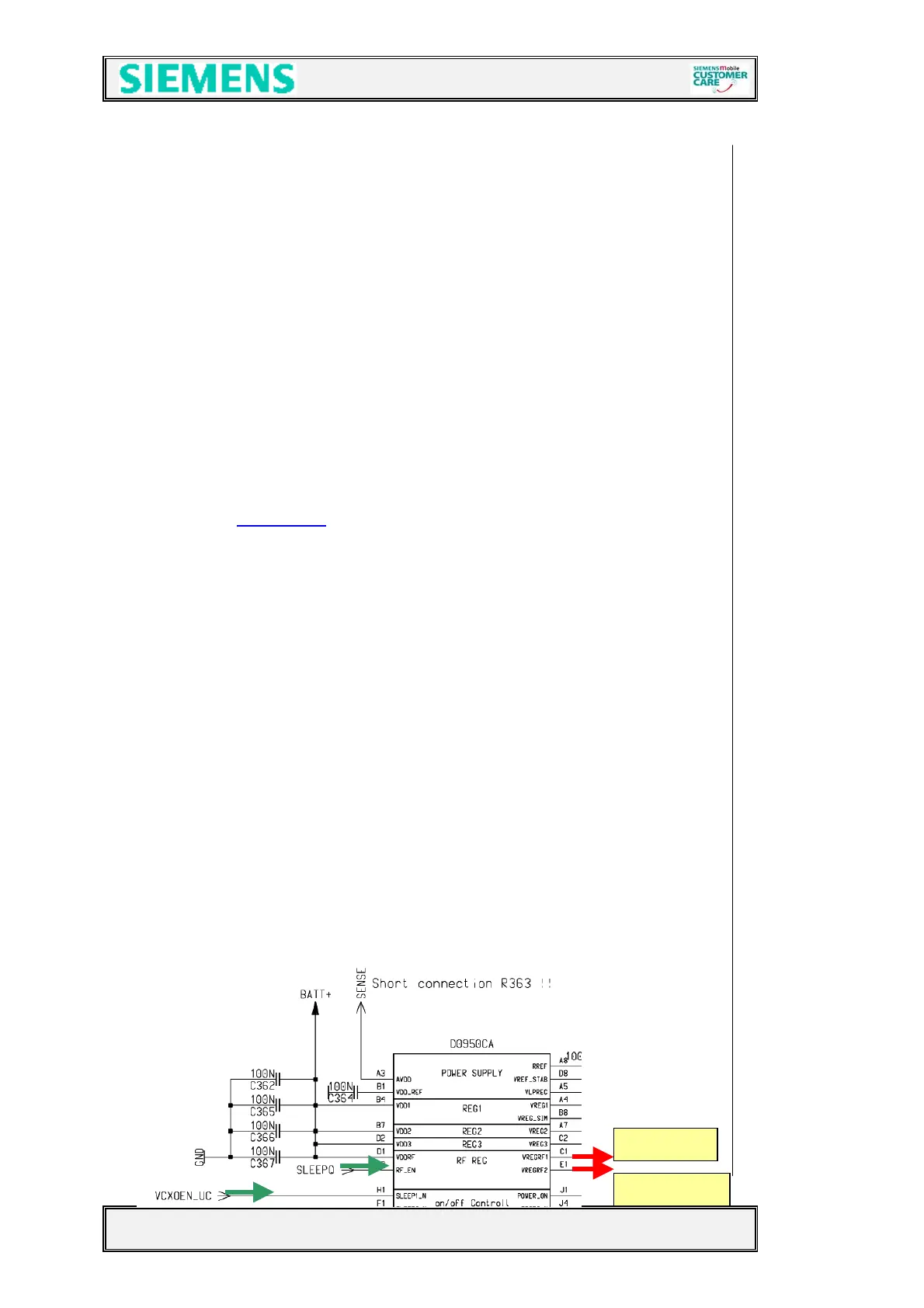
4.1 Power Supply RF-Part
The voltage regulator for the RF-part is located inside the ASIC D361.(see chapter
5.2)
It generates the required 2,8V “RF-Voltages” named VCC2_8 and VCC_SYN . The
voltage regulator is activated as well as deactivated via SLEEPQ
(TDMA-Timer H16) and
VCXOEN_UC
(Miscellaneous R6) provided by the EGOLD+. The temporary deactivation
is used to extend the stand by time.
Circuit diagram
 Loading...