V1.20 Page 9 of 48 ICM MP CCQ GRM
A55/C55_Hitachi Company Confidential © Copyright Siemens AG 04/03
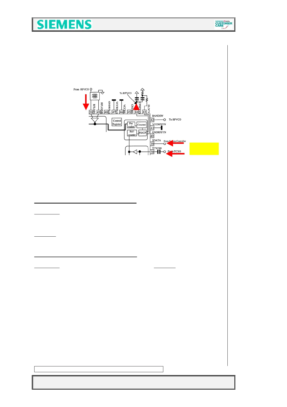
4.2.2 Synthesizer: LO1
The first local oscillator is needed to generate frequencies which enable the
transceiver IC to demodulate the receiver signal and to perform the channel selection
in the TX part. To do so, a control voltage for the LO1 is used. Gained by a
comparator. (located inside the Transceiver (Bright -IC). This control voltage is a result
of the comparison of the divided LO1 and the 26MHz reference Signal. The division
ratio of the dividers is programmed by the EGOLD+, according to the network channel
requirements.
The first local oscillator (LO1) consists of the PLL inside the Bright (D800), an
external loop filter and the VCO (Z850) module. This LO1 circuit generates
frequencies from
3700-3980 MHz for EEGSM900
3580-3760 MHz for GSM1800
Formula to calculate the TX frequencies:
EEGSM900
Channel: 975...1023/76...92 = (Channel freq. + 82MHz) * 4
Channel: 0…75/93…124 = (Channel freq. + 80MHz) * 4
GSM1800
Channel: 512...661 = (Channel freq. + 80MHz) * 2
Channel: 662…885 = (Channel freq. + 82MHz) * 2
Formula to calculate the RX frequencies:
EEGSM900
= Channel freq. * 4 GSM1800 = Channel freq. * 2
The VCO (Z850) is switched on by the EGOLD+ signal PLLON
(TDMA-Timer F16) via
V850 and therefore supplied with VCC2_8. The VCO guarantees by using the control
voltage at pin5 a coverage of the EEGSM900, GSM1800 frequency band and the
frequency stability. The Bright gained control voltage passes on the way to the VCO a
discreet loop filter (typical value from 0,5 – 2,1V). The channel programming of the
PLL happens via the EGOLD+ signals RFDATA; RFCLK; RFSTR.
(RF Control J15, J16,
J17)
. If the Bright IC gets via the same signals a GSM1800 channel information, the
VCO is switched to this frequency by Pin 42 Bright (Pin 3 VCO).
For GSM900 - RX = “low signal” for channel 975-49
= “high signal” for channel 50-124
- TX = “high signal” for all channels
For GSM1800 - RX = “low signal” for all channels
- TX = “low signal” for all channels
The VCO output signal passes the “Balun” transformer (Z851) with insertion losses of
~ 2dB to arrive at the Bright IC.
The required voltage VCC8_8 is provided by the ASIC D361
26MHz
 Loading...