V1.20 Page 18 of 48 ICM MP CCQ GRM
A55/C55_Hitachi Company Confidential © Copyright Siemens AG 04/03
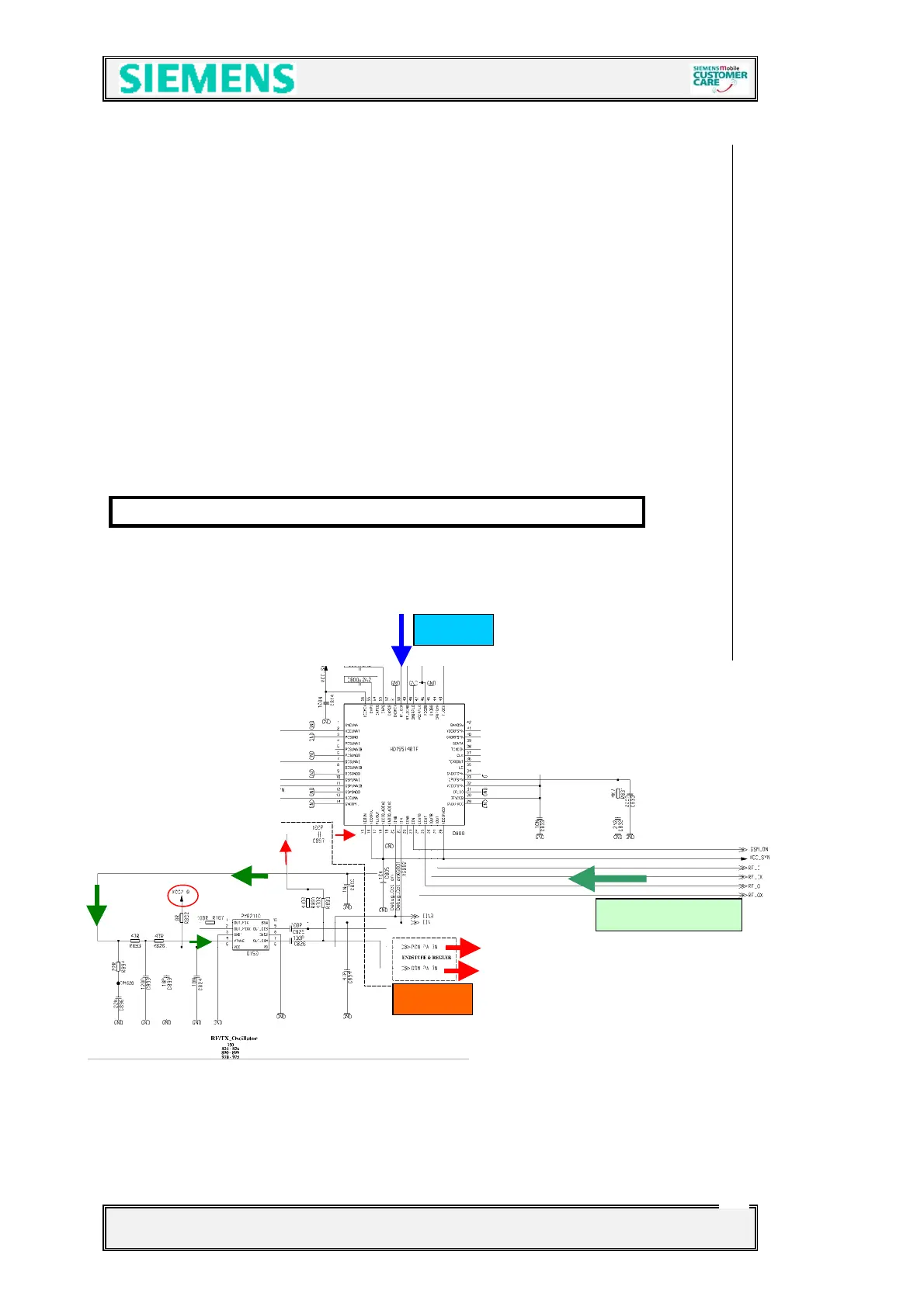
4.5 Transmitter
4.5.1 Transmitter: Modulator and Up-conversion Loop
The modulation is based on the principle of the “up-conversion modulation phase
locked loop” and is accomplished via the BRIGHT IC(D800). An internal TX IF-LO
provides the quadratic modulator with the TX IF frequency of 80/82 MHz by
generating 640/656MHz divided by 8. This so generated IF GMSK RF signal is
compared in a phase detector with the down mixed GMSK RF output from the TX-
VCO (Z150). To get the comparison signal, PCN_PA_IN (for GSM1800), and
GSM_PA_IN (for EGSM900) appearing at Pin 9/7 of the (D150) are mixed with the
LO1 signal (divided by 2 for GSM1800 and 4 for EGSM900). The output (PLLOUT)
signal of the phase detector passes a discrete loop filter realised by capacitors and
resistors to set the TXVCO to required frequency. The large loop band width
(~1,5MHz) guarantees that the regulating process is considerably quicker than the
changes in the modulation signal.
The required voltage VCC_SYN and VCC2_8 is provided by the ASIC D361
to PA
from EGOLD+
LO1
 Loading...