V1.20 Page 19 of 48 ICM MP CCQ GRM
A55/C55_Hitachi Company Confidential © Copyright Siemens AG 04/03
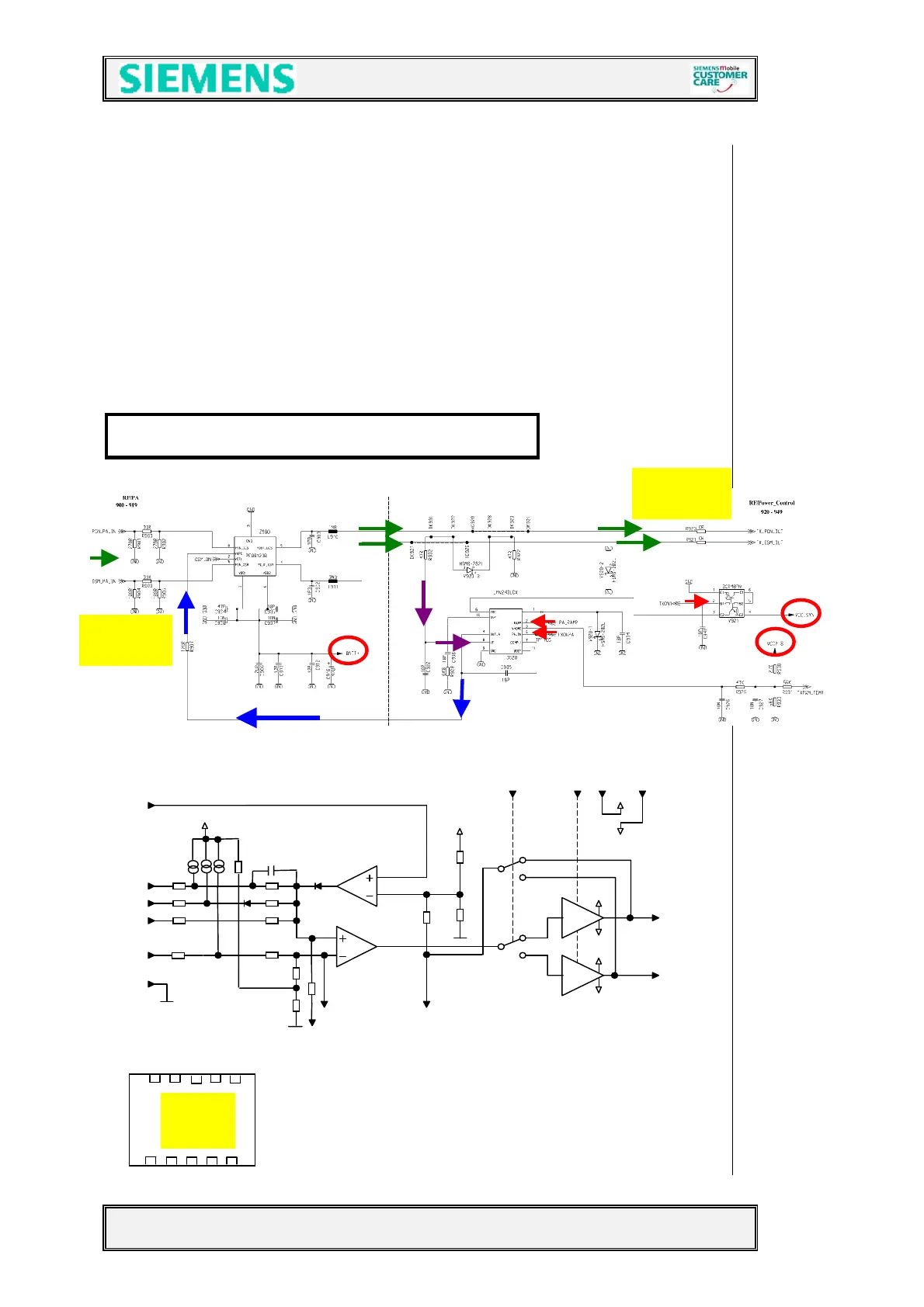
4.5.2 Transmitter: Power Amplifier
The output signals (PCN_PA_IN , and GSM_PA_IN) from the TX-VCO are led to the
power amplifier (Z900) passing a matching circuit. The PA is a “two in one” PA
(EGSM900/GSM1800) and is connected directly to Batt+. The band selection
switching is done via GSM_ON from the Bright IC. After amplification, a part of the
output signals (TX_PCN_OUT and TX_GSM_OUT) is decoupled via a directional
coupler. The other part runs through the antenna switch (Z880) inside the FEM and
the antenna connector (X870) to the Antenna. The decoupled part is equalised by the
detector diode (V920) and used from the RF-Power regulator IC (D920) to get a PA
control voltage, by comparing this voltage with the PA_RAMP signal provided from the
EGOLD+ (
analogue interface J2). The (N920) is activated through the signal TXON1.
TXONPA enables with a “high” signal the output “a” (pin 4).
The required voltage BATT+ is provided by the battery.
The required voltage VCC2_8 is provided by the ASIC D361.
Blockdiagram of LML240 (PA control IC)
Vdd
Vdd
Vss
Vdd
Vdd
Vss
Vdd
Vss
Comp 2
Comp1
Out B
Out
VssVddBS PA_ON
Gnd
TC
Ram
Vr
Vf
Vhom
from TX-
VCO
to Ant.
connector
1 2 3 4 5
10 9 8 7 6
Top
view

 Loading...