Unit Description
8-4
MP270 Equipment Manual
Release 01/99
8.3 Connection elements
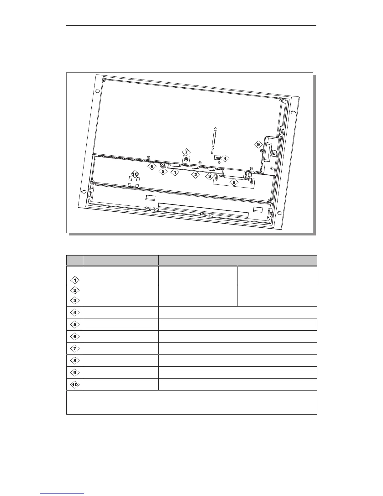
Figure 8-3 Arrangement of connection elements
No. Name Description/Use
Interfaces
1)
: Level: Usage:
IF1A RS232/TTY (active/passive) PLC
IF2 RS232 PC, PU, printer
IF1B
2)
RS422/RS485 (floating) PLC
DIL switch
3)
To configure interface IF1B
Power supply
4)
Connection for power supply (+24 V DC)
Backup battery Connection for optional backup battery
Grounding connection For connection to cabinet ground
Slot A For PC card
Slot B For CF card (not supported at present)
Backup battery Fixation for optional backup battery
1)
Connection pin assignment, see Appendix B.
2)
Use a connection plug with an axial cable output in order to ensure access to the PC card.
3)
Switch settings, see Page 7-9.
4)
Connection pin assignment, see Page 7-6.
 Loading...


