HOA (Hand-Off-Auto) Upgrade Kits
Technical Reference Manual
If a logical point is defined using a physical address that is mapped to an HOA switch
by default the logical point value will correspond to the current Hand and I/O status of
the HOA switch.
The HOA mapping and definition of a logical point in the database can be done in any
order.
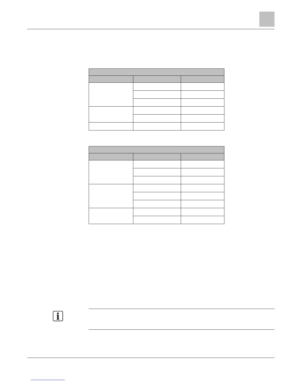
Default Mapping for HOA (8 button)
PXC -16 1-3 DOs 14,15,16
4-6 AOs 9,10,11
7 and 8 Unused
1)
PXC -24 1-5 DOs 20-24
6, 7, 8 AOs 17,18,19
PXC -36 1-8 DOs 29-36
1)
Available for custom mapping.
Default Mapping for HOA (16 button)
PXC -16 1-3 DOs 14,15,16
4-6 AOs 9,10,11
7-16 Unused
1)
PXC -24 1-5 DOs 20-24
6, 7, 8 AOs 17,18,19
9-16 Unused
1)
PXC -36 1-8 DOs 29-36
9-16 Unused
1)
1)
Available for custom mapping.
Communication
When serial connection is made between the host field panel and the HOA module,
communication is established. This initial communication stream consists of the HOA
module providing the host field panel with a unique identifier that provides the
information about the device and its switch capabilities. The Host field panel then maps
each available HOA switch so that is can provide manual override control of the
onboard DOs and AOs.
● The HOA mapping is retained in the database upload.
● After a warmstart, the field panel retains the HOA configuration.
The HOA must be connected to a field panel with Firmware Revision 2.8.5/3.2 or later
in order to backup the HOA database.
 Loading...