45/64
Building Technologies Division User Manual RWF50... CC1U7866en
Infrastructure & Cities Sector 8 Configuration ConF 25.07.2014
8.4 Control outputs OutP
With the RWF50.2, configuration of the outputs relates to the binary outputs (K2 and
K3), and with the RWF50.3, to the analog outputs (A+ and A-). The burner is released
via relay K1.
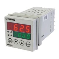
The switching states of relay K1 Burner release (LED green), relay K2 Controlling
element OPEN, and relay K3 Controlling element CLOSE (yellow LED arrows) are
indicated on the controller front.
The binary outputs of the RWF50.2 offer no setting choices.
The RWF50.3 has an analog output.
The analog output offers the following setting choices:
ConF OutP
Parameter Value/
selection
Description
Function
FnCt
Function
1 Analog input
InP1 is delivered
4 Controller’s angular positioning is delivered (modulating controller)
Signal type
SiGn
Type of signal
0 0...20 mA
1 4...20 mA
2 DC 0...10 V
Physical output signal
Value when out of
range
rOut
Value when out of
range
0...101
Signal (in percent) when measuring range is crossed
101 = last output signal
Zero point
OPnt
Zero point
-1999...
0...
+9999
A value range of the output variable is assigned to a physical output signal
End value
End
End value
-1999...
100...
+9999
Only RWV50.2...
Binary outputs
Only RWF50.3...
nalog output
 Loading...


