56/64
Building Technologies Division User Manual RWF50... CC1U7866en
Infrastructure & Cities Sector 12 Technical data 25.07.2014
12.2 Monitoring the measuring circuit
In the event of error, the outputs assume defined states (configurable).
Measuring
transducer
Measured value
crossed limit
Sensor/line has
short-circuit
Sensor/line
interrupted
Resistance
thermometer
● ● ●
Voltage 1...5 V
● ● ●
0...5 V, 0...10 V
(●) --- ---
Current 4...20 mA
● ● ●
0...20 mA
(●) --- ---
● = detected
(●) = detected only if measuring range is exceeded
- = not detected
12.3 Controller outputs OutP Controller o
Relay K1 (NO) 1P, 1N (burner release)
Contact rating Max. 1 A at AC 250 V at cosφ >0.6
Contact life 100,000 switching cycles at high-fire
Contact protection Varistor
Power supply for transducer G+, G-
DC 24 V 10%/max. 25 mA short-circuit-
proof
The following relay data are those specified by the supplier.
Relay K2, KQ (controlling element OPEN)
Contact rating Max. 1 A at AC 250 V and cosφ >0.6
Contact life 100,000 switching cycles at high-fire
Contact protection RC combination
Relay K3, KQ (controlling element CLOSE)
Contact rating Max. 1 A at AC 250 V at cosφ >0.6
Contact life 100,000 switching cycles at high-fire
Contact protection RC unit
Relay data are those specified by the supplier.
Analog output A+, A-
Voltage DC 0...10 V short-circuit-proof
Load resistance R
Last ≥500
Accuracy 0.25%, 50 ppm/K
Current 0...20 mA/4...20 mA
Load resistance RLast 500
Accuracy 0.25%, 50 ppm/K
12.4 Controller
Type of controller
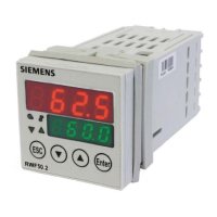
- RWF50.2 Modulating controller
- RWF50.3 Continuous controller
Controller structure P/PI/PD/PID
Sampling time 250 ms
Only RWF50.2
Only RWF50.3
 Loading...


