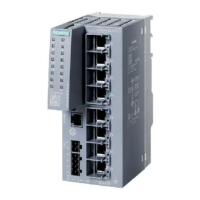
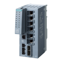
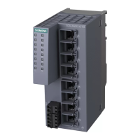
Description of the device
3.3 LED display
SCALANCE XC-100
16 Operating Instructions, 06/2016, C79000-G8976-C415-02
LED display
Fault LED "F" (red LED)
The fault LED indicates the incorrect functioning of the device.
Red Lit The IE switch detects an error. At the same time, the signaling contact opens.
The following faults/errors are detected:
1. Link down event on a monitored port.
2. Loss of the power supply of one of the two redundant power supplies or the pow-
er supply drops below 9.6 V.
3. Both power supplies are below approximately 9.6 V (voltage too low).
Power LEDs “L1” and “L2” (green LEDs)
The power LEDs show the status of the power supply at connectors L1 and L2.
Power supply L1 or L2 is connected.
Power supply L1 and L2 are not connected or L1 and L2 <9.6 V.
Note
If the green LED is not lit, no other signal LED lights up either.
Port LEDs "P" (green/yellow LEDs)
The port LEDs indicate the status of the ports.
Link exists, no data reception at port
Link exists, data reception at port
Setting or display of the fault mask
 Loading...