2-6
PP7,
PP17-I, PP17-II Equipment Manual
Release 06/98
2.2 Define Configuration in PLC
2.2.1 MPI connection
If
connection type MPI is used for the Push Button Panel, no hardware config
-
uration is necessary
. Only the MPI address needs to be set on the Push Button
Panel.
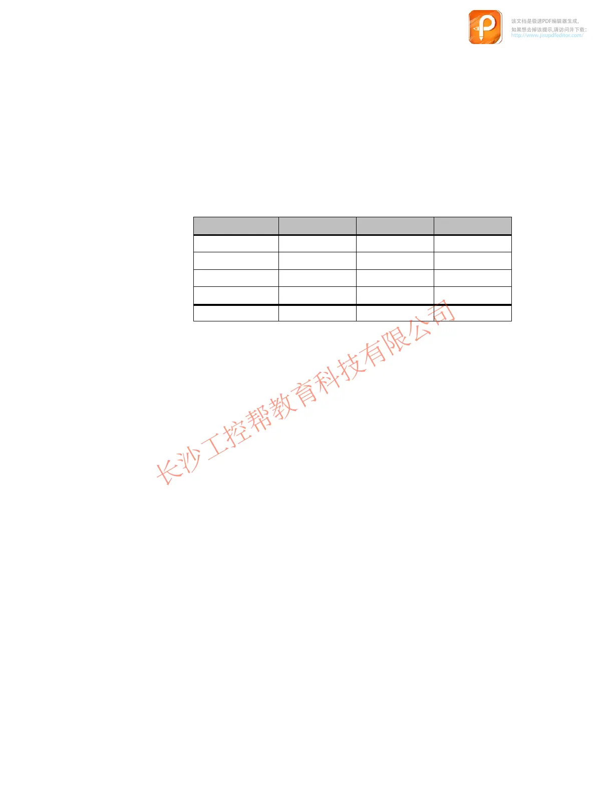
Interrelated memory areas must be set up in the PLC for the keys, LEDs and
digital inputs and outputs. The following table indicates the length of the
memory areas to be set up for the various unit versions.
Memory ar
ea PP7 PP17-I PP17-II
Keys
1 Byte
2 Bytes 4 Bytes
Digital inputs
1 Byte
2 Bytes 2 Bytes
LEDs
2 Bytes 4 Bytes 8 Bytes
Digital outputs
–
4 Bytes 4 Bytes
Total
4 Bytes
12 Bytes 18 Bytes
In order to modify system settings, a data block must be created in the PLC
which contains the configuration data for the Push Button Panel. The structure
of this configuring data block is depicted in Chapter 2.4. The number of the
configuring data block must be specified when configuring the Push Button
Panel.
2.2.2 PROFIBUS-DP connection
When
connection type PROFIBUS-DP is used, the Push Button Panel must be
installed in the PROFIBUS configuration software as a slave in the network. In
the case of SIMA
TIC S5, the configuration software used is COM-PROFIBUS,
and for SIMA
TIC S7 connection to the network is performed via HW
-
CONFIG. The configuration software defines the following:
station address,
the I/O area used
and the configuration of the buttons and LEDs.
Ensure that the same station address is specified that is set on the Push Button
Panel.
该文档是极速PDF编辑器生成,
如果想去掉该提示,请访问并下载:
http://www.jisupdfeditor.com/

 Loading...