Maintenance 12.96
5-4 Siemens AG 6SE7087-6BM70
SIMOVERT MASTER DRIVES Operating Instructions
5.2.6 Removing and installing the module busbars
♦ Removal
• remove the capacitors
• release the bolts holding the module busbars
Bolts M8 power connections
M6 mounting and distance pieces
M4 snubber circuitry
• remove the SMU / SML insulation
• lift out the module busbars
♦ Installation
NOTE
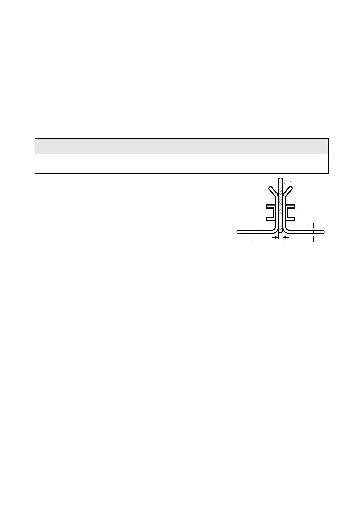
There must be a 4 mm clearance between the positive and negative busbars. Thus, when installing the
module busbars, a template must be used (refer to Fig. 5.2), e.g. a 4 mm-thick plastic piece.
• hold the module busbars and insulation in place SMU / SML (M6)
• the template is inserted in the module busbars instead of the DC link
busbars
• insert the SML- and SMU board (tighten-up the module connections
(M8, torque: 8-10 Nm)
• tighten-up the M6 nut on the distance studs (6 Nm)
• connect-up the snubber resistors (M4 bolts, torque: max. 1.8 Nm)
• tighten-up the power connections (M8 bolts, torque: 13 Nm)
• remove the template from the module busbars.
5.2.6.1 Replacing the balancing resistor
The balancing resistor is located at the rear mounting plane on the heatsink between the inverter modules, i.e.
behind the capacitors and the module busbars.
♦ Remove the capacitors
♦ Type of construction J
• remove the module busbars
• remove IGD
• release the mounting bolts and remove the
balancing resistor.
♦ type of construction K
• release the mounting bolts and remove the
balancing resistor.
Installation in the reverse sequence.
♦ The balancing resistor is tightened-up with 1.8 Nm.
A uniform coating of heat conducting paste must be applied to the base plate.
Observe the correct contact assignment!
Module busbars
+ connection
Module
busbars
- connectio
Template 4 mm
4
Fig. 5.2 Install the module busbars
 Loading...


