08.96 Options
Siemens AG 6SE7087-6BM70
6-3
SIMOVERT MASTER DRIVES Operating Instructions
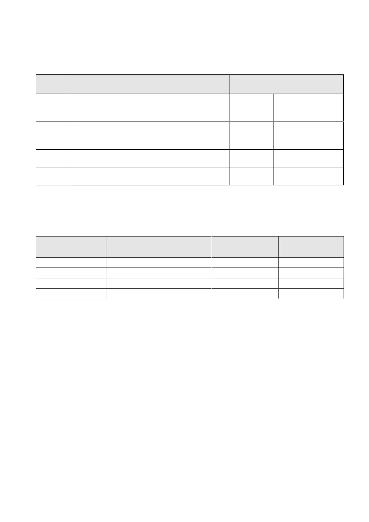
6.2 Interface boards
The boards, listed in the following table must be externally mounted and wired-up on the external system side.
Desig-
nation
Description Order No.
SCI1 Serial I/O board (only in conjunction with SCB1).
Analog and binary input and outputs for coupling to the
SCB1 via fiber-optic cable
Board
description
6SE7090-0XX84-3EA0
6SE7087-6CX84-0BC0
SCI2 Serial I/O board (only in conjunction with SCB1)
Binary inputs and outputs for coupling to the SCB1 via
fiber-optic cable.
Board
description
6SE7090-0XX84-3EF0
6SE7087-6CX84-0BC0
DTI Digital tachometer interface Board
description
6SE7090-0XX84-3DB0
6SE7087-6CX84-3DB0
ATI Analog tachometer interface Board
description
6SE7090-0XX84-3DF0
6SE7087-6CX84-3DF0
Table 6.4 Interface boards
6.3 Power supplies
Designation Description Order number
Option
Use with
Power supply, 0.3 A 115 V / 230 V AC - 24 V 0.3 A DC 6SX7010-0AC14 e.g.: DTI
Power supply 1 A 115 V / 230 V AC - 24 V 1 A DC 6SX7010-0AC15 e.g.: 1 x SCI
Power supply 5 A 115 V / 230 V AC - 24 V 5 A DC 6EP1333-1SL11 Basic conv
Power supply 8 A 115 V / 230 V AC - 24 V 8 A DC Basic conv. + options
Table 6.5 Recommended power supply
 Loading...


