Options 08.96
6-6 Siemens AG 6SE7087-6BM70
SIMOVERT MASTER DRIVES Operating Instructions
6.5.1.1 Output reactor
The output reactor is especially used to limit additional current spikes caused by the cable capacitances when
long cables are used, i.e. it
♦ reduces the charge current spikes for long cables
♦ reduces the voltage rate-of-change dv/dt at the motor terminals.
It does
not reduce the magnitude of the transient voltage spikes at the motor terminals.
In order that the reactor temperature rise remains within the specified limits, the pulse frequency f
p
of the drive
converter, rated motor frequency f
mot N
and the maximum drive converter output frequency f
max
must lie within
the specified limits:
V/f = constant V = constant
510 V
to 620 V DC
675 V
to 930 V DC
510 V
to 620 V DC
675 V
to 930 V DC
Standard reactor (iron) f
P
≤
3 kHz
V/f / Vector control f
mot N
≤
87 Hz f
mot N
≤
200 Hz f
max
≤
200 Hz f
max
≤
300 Hz
V/f textile f
mot N
= f
max
≤
120 Hz not possible not possible not possible
Ferrite reactor f
P
≤
6 kHz
V/f / Vector control f
mot N
≤
150 Hz f
max
≤
300 Hz
V/f textile f
mot N
= f
max
≤
600 Hz not possible
Table 6.9 Output reactor design
1 output reactor
2 output reactorss
(not permissible for ferrite reactors)
1000100101
100
200
300
400
500
600
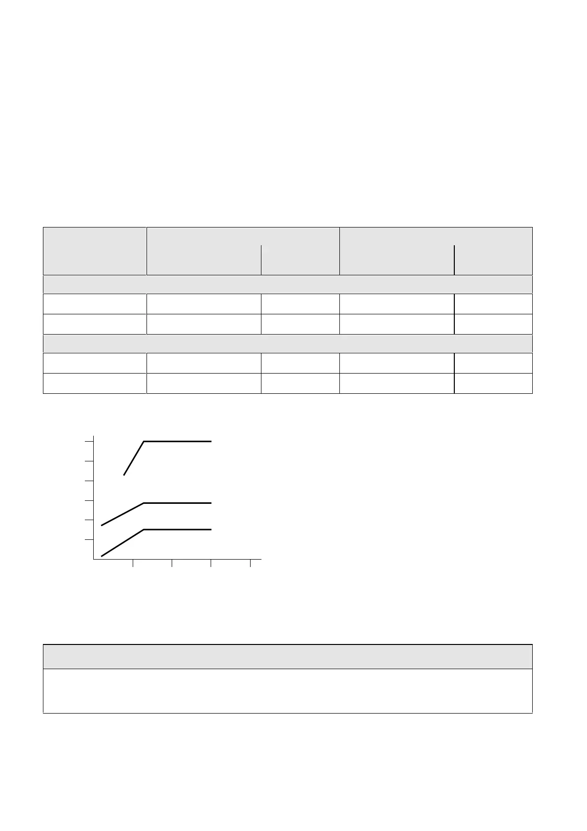
Max. cable length / m
Drive converter outputs / kW
without output reactor
Fig. 6.4 Permissible cable lengths with and without output reactors
NOTE
The specified lengths are valid for unshielded cables; for shielded cables, these values must be reduced to 2/3.
If several motors are connected to a drive converter, the sum of the cables lengths of all the motor feeder
cables must be less than the permissible cable length.
 Loading...


