08.96 Options
Siemens AG 6SE7087-6BM70
6-9
SIMOVERT MASTER DRIVES Operating Instructions
6.6 Bypass- and output contactor
6.6.1 Bypass contactor (electrical DC link
coupling)
Using the electrical DC link coupling, it is possible, for a
multi-motor group with common DC bus, to connect or
disconnect a converter with DC supply input to the DC
bus.
This option is used when an inverter section has to be
replaced.
Binary output -X9:4,5 is provided to control the contactor.
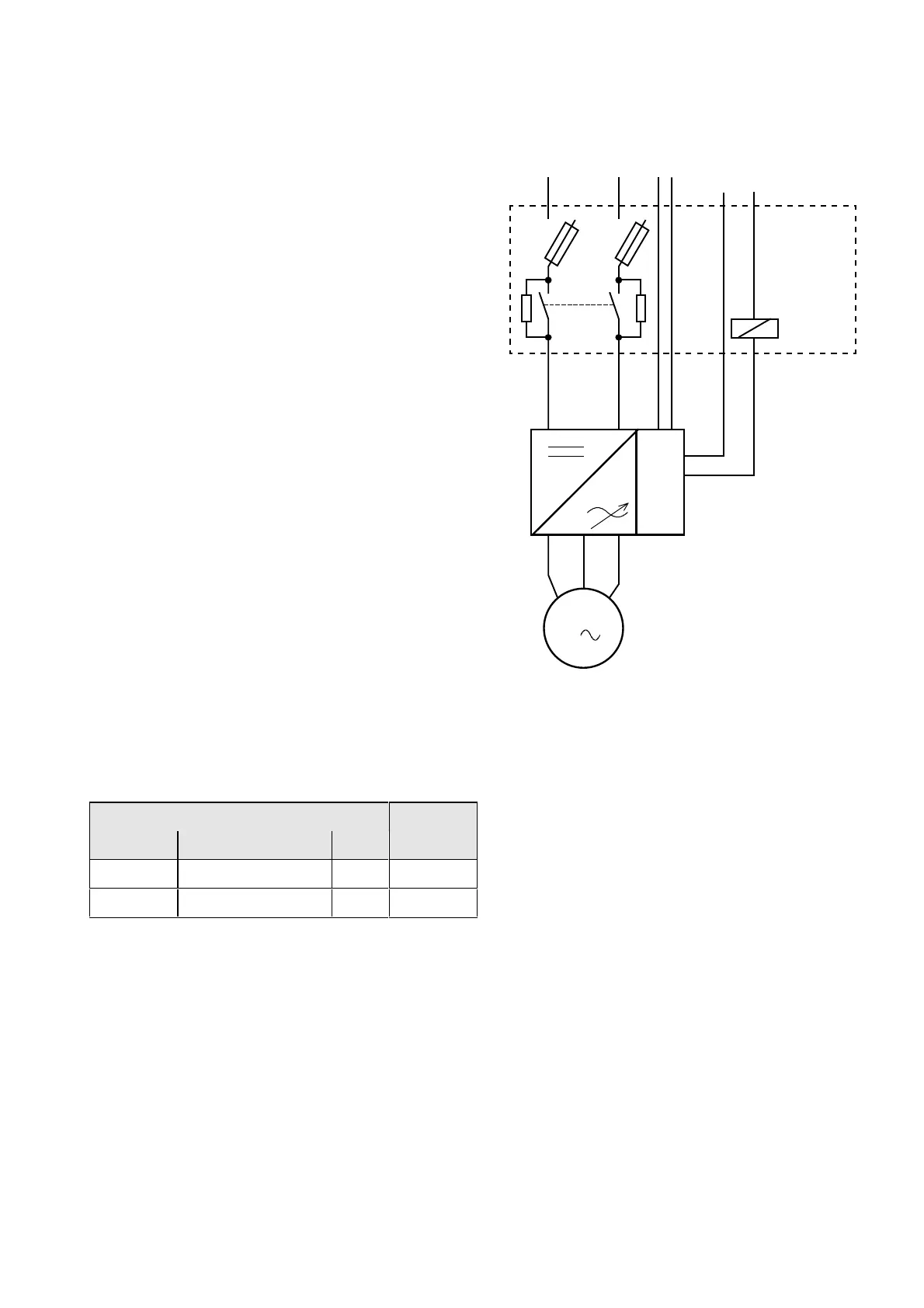
6.6.1.1 Bypass contactor without I/R unit
Parameterization for operation with bypass contactor:
Parameter- Terminal
No. Name Value
P612, i001
ST. MC energized 0000 X9: 4,5
P629, i001
ST.BC energized 1001 X9: 4,5
Table 6.11 Parameterization for the bypass contactor
(electrical DC link coupling)
-X1
C/
L+
D/
L-
DC24 V
Auxiliary voltage
bypass contactor
Electrical DC
link coupling
-X2
C/L+ D/L-
-K10
-K10
12-X9
U2/
T1
V2/
T2
W2/
T3
-X9:4
-X9:5
M
3
Fig. 6.6 Connecting-up example for the bypass contactor
 Loading...


