SIPART DR19
C73000-M7474-C34-4
30
4.3 Removal of the backplane
The backplane may only be removed when the mains
connector and, where appropriate, the 3-pole Δy
connector are disconnected!
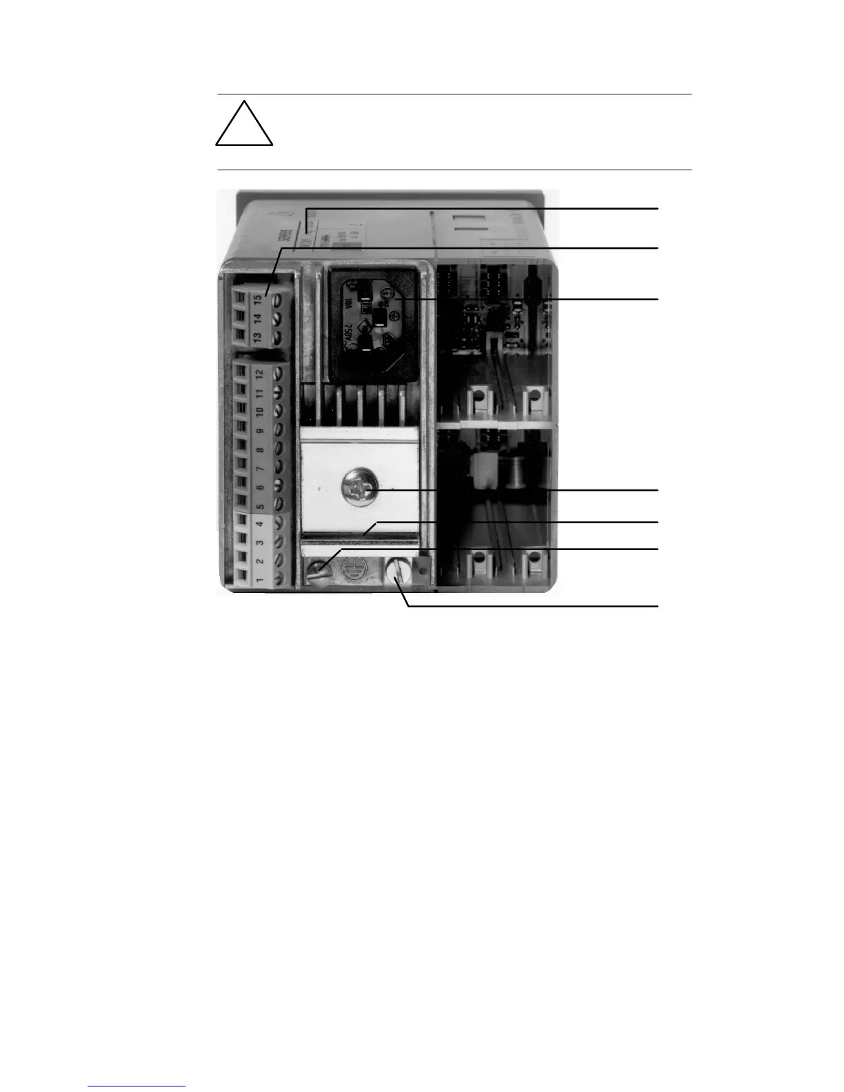
Rear view of
the controller
(1) Rating plate and 2 adhesive 115 V AC labels (initial setting: 230 V AC)
(2) Connector for ±Dy-outputs
(3) Mains connector
(4) Fixing screw for DIN rail
(5) 35 mm DIN rail (DIN EN 50022) supplied with the coupling relay
modules 6DR2804-8A and 6DR2804-8B
(6) Screw for fixing backplane
(7) Screw for protective earth/ground terminal
(1)
(2)
(7)
(4)
(5)
(6)
(3)
Loosen the screw (6).
Remove the backplane from the housing.
Important
!
Procedure
 Loading...


