SIPART DR19
C73000-M7474-C34-4
42
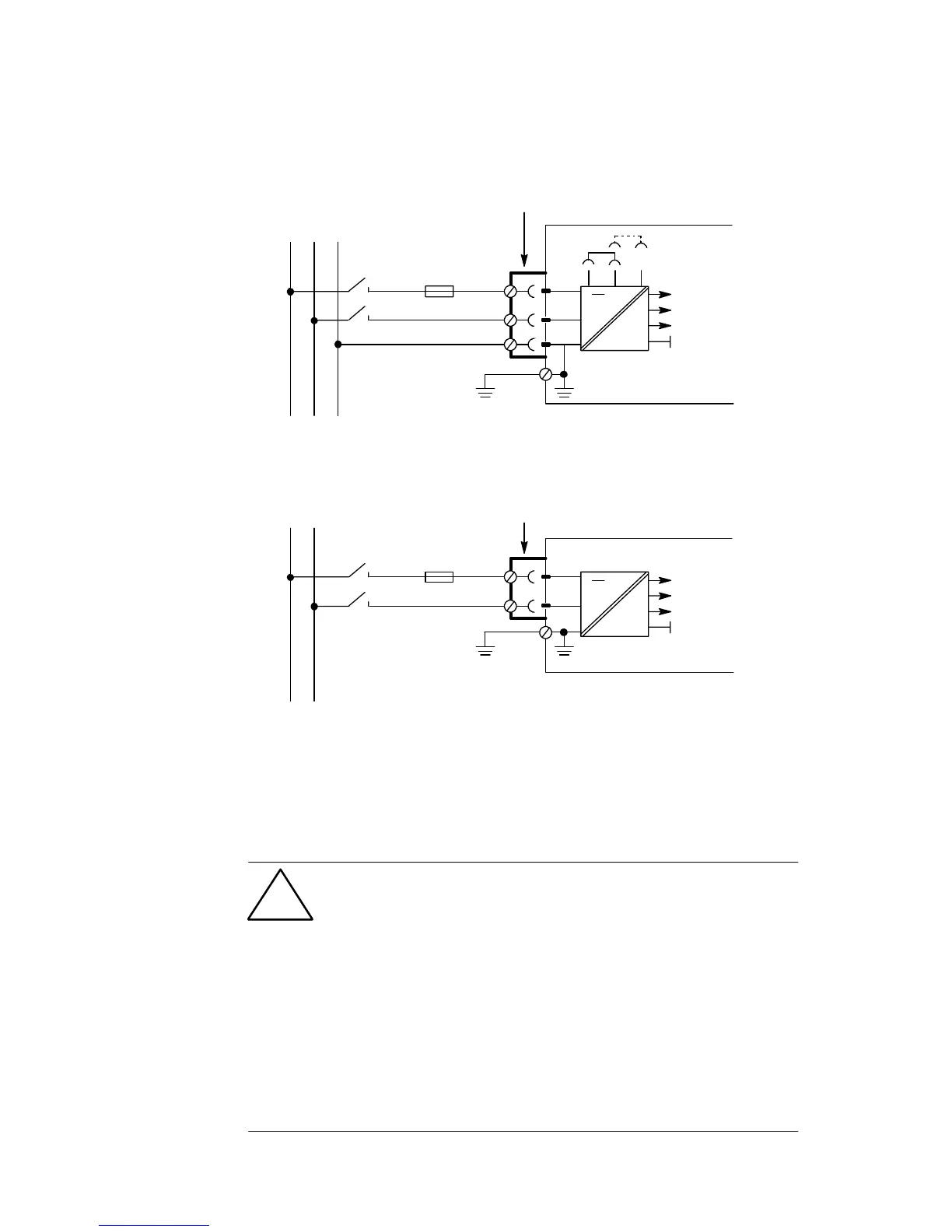
9 Connecting the controller to the supply
voltage
~
=
+24 V
+5 V
U
REF
1,6 A T
per device
1)
L
N
2-pole connector
either pol arity
~
=
+24 V
+5 V
U
REF
0,63A, T at 115 V
0,315A, T at 230 V
per device
1)
L
N
Inlet connector IEC 320 IV
DIN 49457A
230
115
PE
LNPE
115 or 230 V AC
Connecting the
230V AC/115V AC
version
Connecting the
24V AC/DC
version
24 V UC
1)
For high-tolerance electromagnetic compatibility (EMC) in 115/230 V units,
the screw connection for the protected earth terminal (page 30, pos. 7) to
ground must be additionall y provided.
This connection must also be low-impedance for high frequencies (copper
rod or HF litz wire). Otherwise a 2,5V litz wire should be used.
Connected to the mains power supply v ia a 2-pole switch
intheaccessibleregion(fireprotectionaccordingtoIEC
66E (sec) 22/DIN VDE 0411 part 100). For circuits
without limitations, the power supply to the device must
be provided via a switch. For circuits with limitations
(≤30 Vrms or ≤42.4 V DC and current ≤8 A or source
under all loading conditions ≤150 VA or fuse link
corresponding to ≤150 VA ) a switch is not required.
If the 24 V UC power supply unit is secured with ≤4A
(35 V DC) (T 3.15 A as a min. requirement) the switch is
not required.
Important!
!
 Loading...


