2.5 Time Overcurrent Protection for Earth Current
181
7UT613/63x Manual
C53000-G1176-C160-2
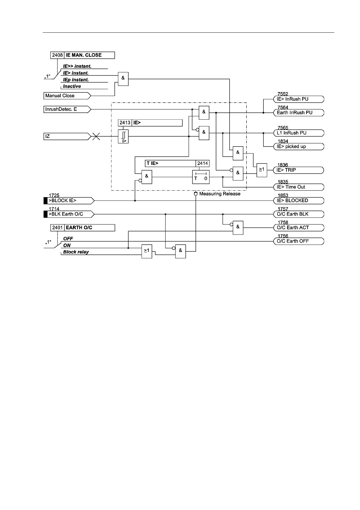
Figure 2-79 Logic diagram of the overcurrent stage I
E
> for earth current (simplified)
2.5.3 Inverse Time Overcurrent Protection
The inverse time overcurrent stage operates with a characteristic either according to
the IEC- or the ANSI-standard or to a user-defined characteristic. The characteristics
and their equations are given in the „Technical Data“. When configuring one of the
inverse time characteristics, definite time stages IE>> and IE> are also enabled.
Pickup, Trip The current measured at the assigned 1-phase current input is compared with setting
value IEp. If the current exceeds 1.1 times the set value, the stage picks up and an
annunciation is made. If inrush restraint is used, a frequency analysis is performed
first. If an inrush condition is detected, pickup annunciation is suppressed and an
inrush message is output instead. The RMS value of the fundamental is used for the
pickup. During the pickup of an I
Ep
stage, the tripping time is calculated from the
flowing fault current by means of an integrating measuring procedure, depending on
the selected tripping characteristic. After expiration of this time period, a trip command
is output as long as no inrush current is detected or inrush restraint is disabled. If
inrush restraint is enabled and inrush current is detected, there will be no tripping. Nev-
ertheless, an annunciation is generated indicating that the time expired.
The following figure shows the logic diagram of the inverse-time overcurrent protection
function.
 Loading...


