2.15 Overvoltage Protection
261
7UT613/63x Manual
C53000-G1176-C160-2
busbar, the pickup value must be set as reference value under address 5312 U>, e.g.
1.20. When assigned to a measuring location, the value of phase-phase voltage must
be set under address 5311 U> in Volt , e.g. 132. V at U
N sec
= 110 V (120 % of 110 V).
The corresponding delay time T U> (address 5313) should amount to a few seconds
so that short-term overvoltages do not result in a trip.
The U>> stage is provided for high overvoltages of short duration. Here, an corre-
spondingly high pickup value is set, e.g. 1.3 to 1.5 times the rated voltage. If the over-
voltage protection is assigned to one side of the main protected object or the three-
phase busbar, the pickup value must be set as reference value under address 5315
U>>, e.g. 1.30. When assigned to a measuring location, the value of phase-phase
voltage must be set under address 5314 U>> in Volt , e.g. 130. V at U
N sec
=100V.
For the delay T U>> (address 5316) 0.1 s to 0.5 s are sufficient.
In generators or transformers with voltage regulator, the settings also depend on the
speed with which the voltage regulator regulates voltage variations. The protection
must not intervene in the regulation process of the faultlessly functioning voltage reg-
ulator. The two-stage characteristic must therefore always be above the voltage time
characteristic of the regulation procedure.
All setting times are additional time delays which do not include the operating times
(measuring time, dropout time) of the protective function. If a delay time is set to ∞,
this does not result in a trip, however, the pickup is indicated.
Dropout Ratio The drop-out ratio can be adjusted to the operating conditions at address 5317 DOUT
RATIO. This parameter can only be altered in DIGSI at Additional Settings.
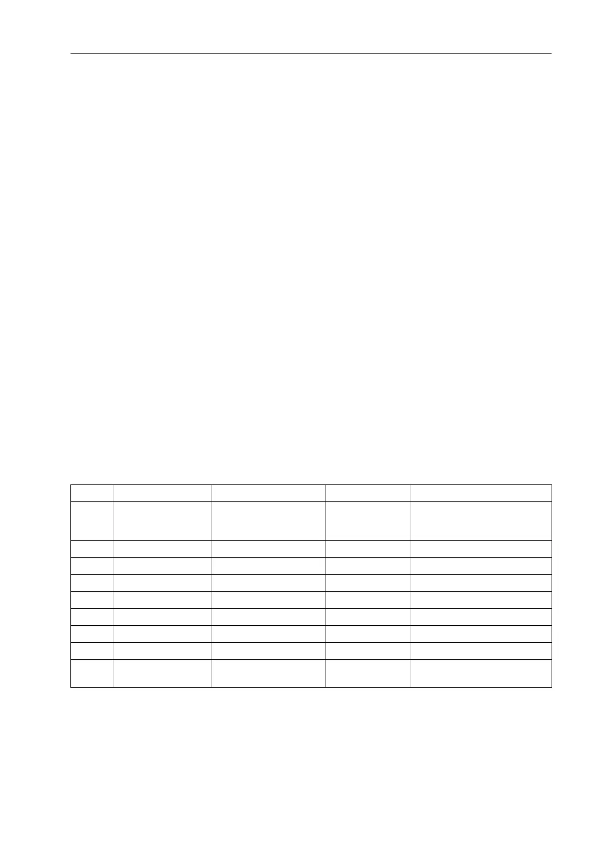
2.15.3 Settings
Addresses which have an appended "A" can only be changed with DIGSI, under Ad-
ditional Settings.
Addr. Parameter Setting Options Default Setting Comments
5301 OVERVOLTAGE OFF
ON
Block relay
OFF Overvoltage Protection
5311 U> 30.0 .. 170.0 V 115.0 V U> Pickup
5312 U> 0.30 .. 1.70 U/UnS 1.15 U/UnS Pick-up voltage U>
5313 T U> 0.00 .. 60.00 sec; ∞ 3.00 sec T U> Time Delay
5314 U>> 30.0 .. 170.0 V 130.0 V U>> Pickup
5315 U>> 0.30 .. 1.70 U/UnS 1.30 U/UnS Pick-up voltage U>>
5316 T U>> 0.00 .. 60.00 sec; ∞ 0.50 sec T U>> Time Delay
5317A DOUT RATIO 0.90 .. 0.99 0.95 U>, U>> Drop Out Ratio
5318A VALUES U-ph-ph
U-ph-e
U-ph-ph Measurement Values
 Loading...


