Mounting
7.1 Installation guidelines
SIRIUS - SIRIUS 3RA load feeders
Manual, 09/2016, A5E03656507520A/RS-AB/003
37
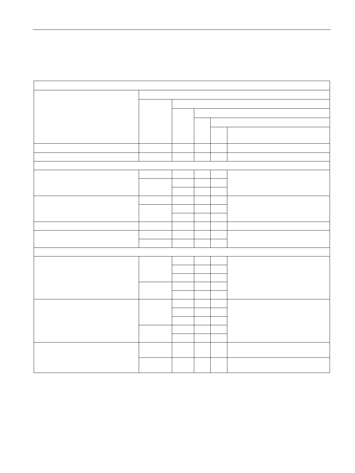
The following table shows the installation guidelines for the fuseless load feeders.
Table 7- 4 Mounting variants - fuseless load feeders with link module
Combination
Setting range
Distance between feeders
Permissible installation: h = horizontal, v = vertical
Max. ambient temperature T
a
Use under increased vibration and shock
load
1)
Motor starter protector and contactor
mm h, v °C
Direct-on-line starter, screw terminal, DIN rail or base plate
S00 ≤ 14 0 h, v 60 Unlimited
> 14 … 16 10 h 60
0 h, v 40
S0 ≤ 29 0 h, v 60 Unlimited
> 29 … 32 10 h 60
0 h, v 40
S2 ≤ 65 0 h, v 60 Unlimited
S3 (with DIN rail adapter 3RA2942-1AA00
only)
≤ 87 0 h, v 60 On request
> 87 ... 100 0 h, v 40
Direct-on-line starter, screw terminal, busbar
S00 ≤ 14 0 h 40 Vibration and shock kit 8US1998-1CA10
required
10 h 60
10 v 40
> 14 … 16 10 h 60
10 h, v 40
S0 ≤ 29 0 h 40 Vibration and shock kit 8US1998-1CA10
required
10 h 60
10 v 40
> 29 … 32 10 h 60
10 h, v 40
S2 ≤ 65 10 h, v 60 Vibration and shock kit 8US1998-1DA10
required
≤ 65 0 h, v 40 Vibration and shock kit 8US1998-1DA10
required
 Loading...


