User Manual of A90 Series Inverter
15
Digital setting, analog input setting, high-speed pulse input setting, communication
setting, digital potentiometer setting, process PID setting, simple PLC setting or
multi-segment speed setting can be performed separately or in a mixed manner. Fig. 1-1 to
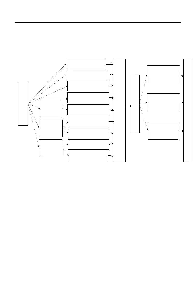
Fig. 1-4 detail various input modes of the A90 series inverter by speed setting.
Setting of main frequency
source A
Setting of auxiliary frequency
source B
Options of frequency
source
F00.06
Setting of main and auxiliary
operations
Setting of main and auxiliary
operations
0
1
2
Frequency
source switching
DI:26
Frequency source
switching
DI:26
Frequency source
switching
DI:26
3
4
5
Setting of auxiliary frequency
source B
Setting of main frequency source
A
Setting of main frequency
source A
Setting of auxiliary frequency
source B
Setting of main and auxiliary
operations
N
Y
N
Y
N
Y
Synthetic frequency gain of main and auxiliary
channels
F00.12
Analog adjustment options
F00.13
0: synthetic frequency of
main and auxiliary
channels
1: AI1 * synthetic
frequency of main and
auxiliary channels
2: AI2 * synthetic
frequency of main and
auxiliary channels
0
1
2
Limit of the set frequency: F00.16; direction: F00.21
etc.
Fig. 1-1 Schematic Diagram of Speed Input Mode
As shown in Fig. 1-1, speed setting of A90 series inverter is mainly divided into the
setting of main frequency source A (referred to as “main A”), setting of auxiliary frequency
source B (referred to as “auxiliary B”), and setting of main and auxiliary operations. The
final settings are made by simply adjustment and limitation (e.g. upper frequency limit,
maximum frequency limit, direction limit, frequency hopping limit). For details, see Fig.
1-2 to Fig. 1-4.
 Loading...