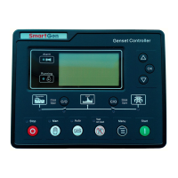
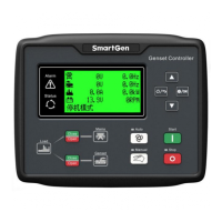
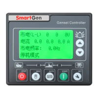
HGM400 Series Genset Controller User Manual
HGM400 Series Genset Controller ISSUE 2015-05-27 Version 1.6 Page 41 of 44
CAUTION! Let its normally closed contact series connect between fuel relay
output port and electromagnetic valve when you connect emergency stop button on
the controller. Emergency stop alarm can be displayed if you configure one input port
as “Emergency Shutdown” (one end connect to normally open contact, the other end
connect to ground).
12 INSTALLATION
12.1 FIXING CLIPS
Controller is panel built-in design; it is fixed by clips when installed.
1) Withdraw the fixing clip screw (turn anticlockwise) until it reaches proper position.
2) Pull the fixing clip backwards (towards the back of the module) ensuring two clips
are inside their allotted slots.
3) Turn the fixing clip screws clockwise until they are fixed on the panel.
Note: Care should be taken not to over tighten the screws of fixing clips.
 Loading...
