- 23 -
6. Details of Power Supply Plug
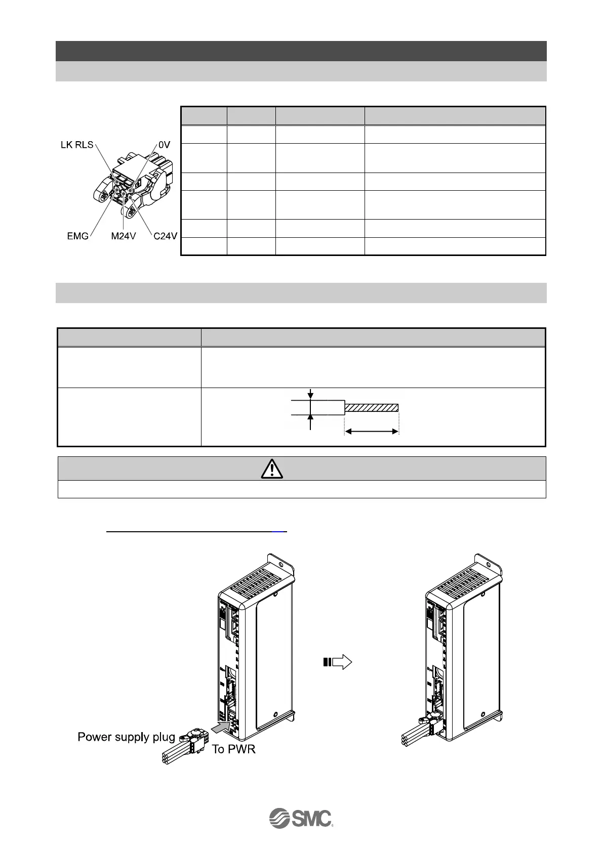
6.1 PWR: Power supply plug specifications
The specifications of the power supply plug supplied with the controller are shown below.
The positive control power.
The positive power for the actuator
motor to be supplied via the controller.
The positive power for Stop signal
The negative common power for M24V,
C24V, EMG and LK RLS.
The positive power for lock release.
Equivalent to Phoenix Contact: DFMC1, 5/3-ST-LR
6.2 Electrical Wiring Specifications
Prepare the electrical wiring according to the following specifications (to be prepared by the user).
Single, stranded wire → AWG20 (0.5mm
2
)
The rated temperature of the insulation coating should be 60
o
C or more.
The O.D. should be ø2.5mm or less.
Do not connect multiple wires to one terminal.
After wiring the power supply plug, connect it to PWR power connector of the controller.
Refer to 6.3 Power Supply Plug Wiring (P.24) for wiring.
Power supply plug inserted into CN1

 Loading...


