- 55 -
[5] Reset
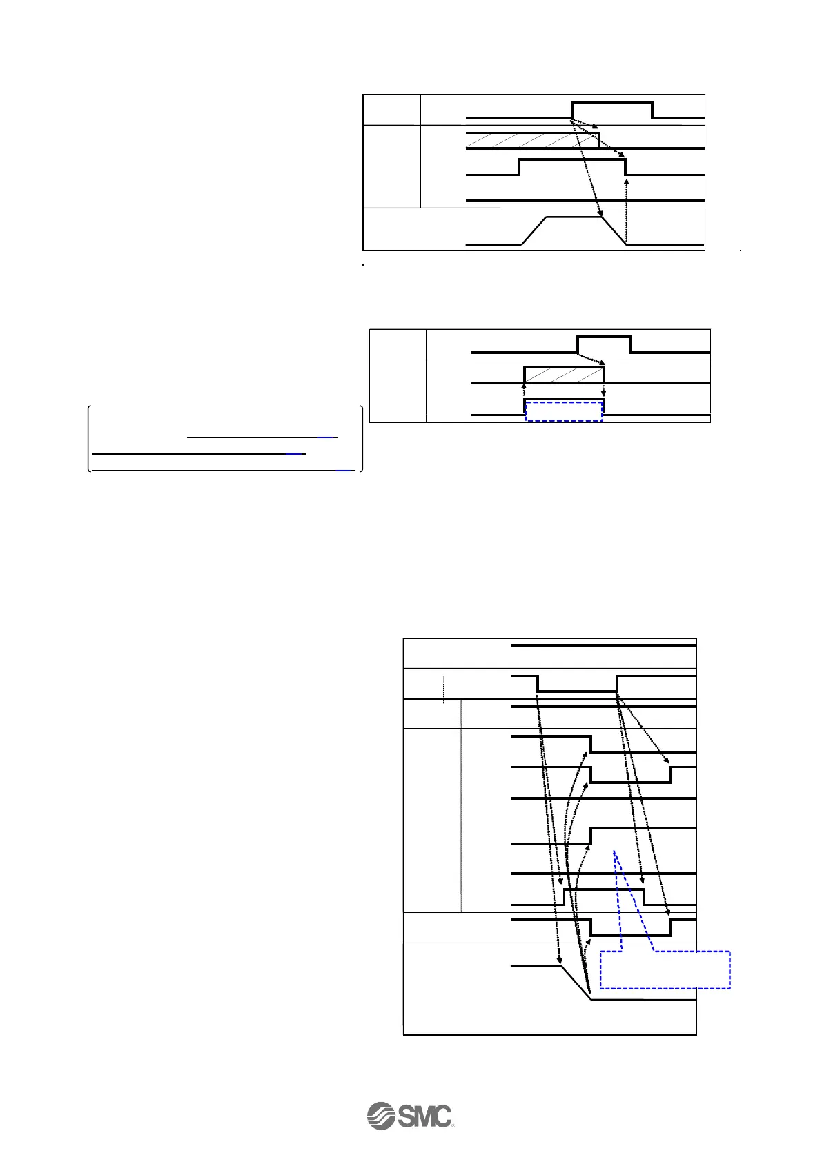
-Procedure- [Driving reset] - Timing chart - Reset
(1) During operation (“BUSY” is ON)
“RESET" is turned ON.
(2) “BUSY” and “OUT0” to “OUT5” are OFF.
(3) The actuator decelerates to stop
(controlled).
-Procedure- [Alarm Reset]
(1) Alarm generated
“ALARM” turns ON.
Alarm group is output to “OUT0” to
“OUT3”.
Alarm code is output.
For memory to be checked and detailed,
Please refer to 9. Memory map (P.30)
15.1 Alarm group signals (P.62)
15.3 Alarms and countermeasures (P.64)
(2) Turn ON "RESET".
(3) "ALARM" turns OFF, OUT0 to
OUT3 turn OFF. (The alarm is
deactivated).
[6] Stop
- Procedure - - Timing chart -
(1) During operation ("BUSY" is ON),
turn OFF "EMG". (Stop command)
(2) "ESTOP" turns ON.
(3) "BUSY" turns OFF. (The actuator stops.)
“SVRE” turns OFF.
The actuator with lock is locked.
(4) Turn ON "EMG".(The stop release
command)
(5) "ESTOP" turns OFF.
"SVRE" turns ON.
The actuator with lock is unlocked.
If the now position is inside of step
data positioning, the INP signal is
ON.
Otherwise OFF.

 Loading...


