EasyManuals Logo
Home>SMC Networks>Controller>JXCP1

SMC Networks JXCP1 User Manual

SMC Networks JXCP1
87 pages
To Next Page IconTo Next Page
To Previous Page IconTo Previous Page
Page #29 background imageLoading...
Page #29 background image
- 28 -
7. LED display
7.1 LED display
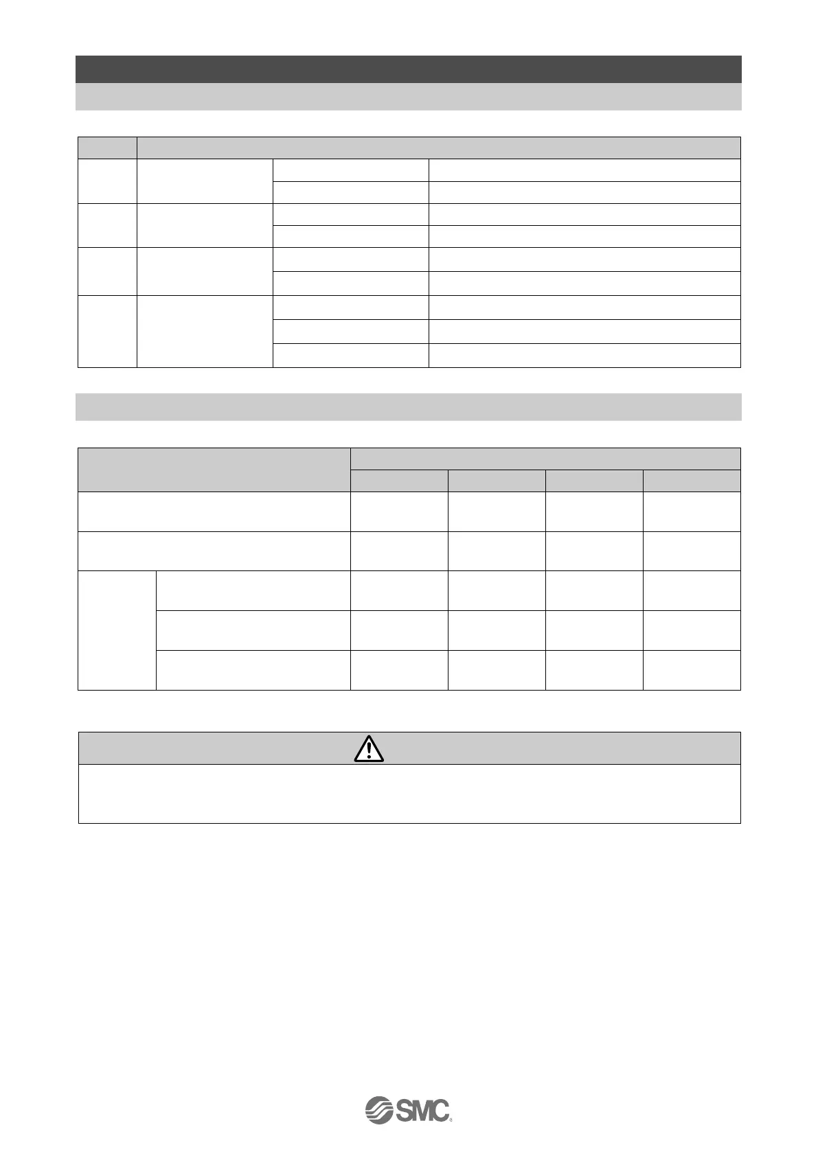
Refer to the table below for details of the LED status.
LED
Details
PWR
Power supply
status.
OFF
Power is not supplied
Green LED is ON
Power is supplied
ALM
Controller alarm
status.
OFF
Normal operation
Red LED is ON
Alarm generated
SF
Controller status.
OFF
Normal operation
Red LED is ON
Alarm generated (Linked to ALM)
BF
PROFINET
communication
status
OFF
PROFINET communication is established.
Red LED is flashing
PROFINET communication is not established.
Red LED is ON
Both Port1 and Port2 are not connected.
7.2 LED and Controller Status
Refer to the table below for the LED and the controller status.
Controller status
LED description
PWR
ALM
SF
BF
When power is supplied
Green LED
is ON
LED is OFF
-
-
When PROFINET communication is
normal
-
-
LED is OFF
LED is OFF
Motor
controller
Controller alarm generated
LED is OFF
Red LED is
ON
Red LED is
ON
-
Controller system error
generated
Green LED
is ON
Red LED is
ON
-
-
Writing to controller
EEPROM
Green LED
is flashing
-
-
-
-: LED display is unstable
Caution
Do not turn OFF the power supply for the controller or disconnect and connect the cable while data is
being written to EEPROM (PWR LED (green) is flashing).
This is to avoid the possibility of incorrect / corrupt data (step data, parameter)

Table of Contents

Questions and Answers:

Question and Answer IconNeed help?

Do you have a question about the SMC Networks JXCP1 and is the answer not in the manual?

SMC Networks JXCP1 Specifications

General IconGeneral
BrandSMC Networks
ModelJXCP1
CategoryController
LanguageEnglish

Related product manuals