- 40 -
●Byte28-31: AREA 2
Basic parameter
"Stroke (-)" - "Stroke (+)" (5, 7, 11)
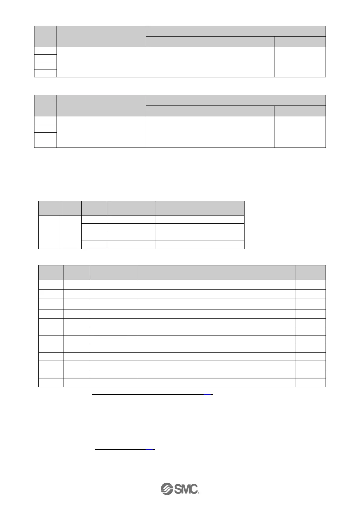
(5) Record data (request sent from PROFINET master to JXCP1 controller)
A record request is used to update the Step data items stored in the JXCP1 controller.
●Record data object
Record Data
Length (Byte)
●Details of Record Data Index
1:ABS (Absolute) 2:INC (Relative) (10, 14)
1 to “Max speed” of the basic parameter (5, 11, 14)
Basic parameter "Stroke(-)" - "Stroke (+)" (5, 11, 14)
1 to “Max ACC” of the basic parameter (5, 11, 14)
1 to “Max DEC” of the basic parameter (5, 11, 14)
Pushing force
(Thrust setting
value)
Basic parameter "Stroke(-)" - "Stroke (+)" (5, 11, 14)
Basic parameter "Stroke(-)" - "Stroke (+)" (5, 11, 14)
Basic parameter "Stroke(-)" - "Stroke (+)" (5, 11, 14)
5 Please refer to 20. Handling of sent/received data (P.84) for handling of the data.
7 Change the numerical data input flag and the numerical data, when the start flag is OFF
If the numerical data input flag and the numerical data are changed when the start flag is ON, it
might lead to unexpected operation.
10 Do not input numbers other than [1(ABS)] and [2(INC)].
11 The actuator model determines the limit for the input values. Please refer to the manual of the
actuator for more details.
12 Please refer to “●Details of Record Data Index” for details of each index.
13 Please refer to 10.1 Step Data(P.42) for details of Step Data items.
14 Change the Step data items in Record Data while stopping. If the Step data items in Record Data
are changed while operating, it might lead to unexpected operation.

 Loading...


