EasyManua.ls Logo

Sony 5500 User Manual

Sony 5500
187 pages
To Next Page IconTo Next Page
To Previous Page IconTo Previous Page
Page #2 background imageLoading...
Page #2 background image
2
Read these instructions.
Keep these instructions.
Heed all warnings.
Follow all instructions.
Do not use this apparatus near water.
Clean only with dry cloth.
Do not block any ventilation openings.
Install in accordance with the manufacturer’s
instructions.
Do not install near any heat sources such as radiators,
heat registers, stoves, or other apparatus (including
amplifiers) that produce heat.
Do not defeat the safety purpose of the polarized or
grounding-type plug. A polarized plug has two blades
with one wider than the other. A grounding-type plug
has two blades and a third grounding prong. The wide
blade or the third prong are provided for your safety. If
the provided plug does not fit into your outlet, consult an
electrician for replacement of the obsolete outlet.
Protect the power cord from being walked on or pinched
particularly at plugs, convenience receptacles, and the
point where they exit from the apparatus.
Only use attachments/accessories specified by the
manufacturer.
Use only with the cart, stand, tripod, bracket,
or table specified by the manufacturer, or sold
with the apparatus.
When a cart is used, use caution when moving
the cart/apparatus combination to avoid injury from tip-
over.
Unplug this apparatus during lightning storms or when
unused for long periods of time.
Refer all servicing to qualified service personnel.
Servicing is required when the apparatus has been
damaged in any way, such as power-supply cord or plug
is damaged, liquid has been spilled or objects have fallen
into the apparatus, the apparatus has been exposed to
rain or moisture, does not operate normally, or has been
dropped.
To prevent fire or shock hazard, do not
expose the unit to rain or moisture.
To avoid electrical shock, do not open the
cabinet. Refer servicing to qualified
personnel only.
THIS APPARATUS MUST BE EARTHED.
WARNING: THIS WARNING IS APPLICABLE
FOR USA ONLY.
If used in USA, use the UL LISTED power
cord specified below.
DO NOT USE ANY OTHER POWER
CORD.
Plug Cap Parallel Blade with ground pin
(NEMA 5-15P Configuration)
Cord Type SJT, three 16 or 18 AWG
wires
Length Minimum 1.5 m (4 ft 11 in), less
than 2.5 m (8 ft 3 in)
Rating Minimum 10 A, 125 V
Using this unit at a voltage other than 120 V
may require the use of a different line cord
or attachment plug, or both. To reduce the
risk of fire or electric shock, refer servicing
to qualified service personnel.
WARNING: THIS WARNING IS APPLICABLE
FOR OTHER COUNTRIES.
1. Use the approved Power Cord (3-core mains lead)/
Appliance Connector/Plug with earthing-contacts that
conforms to the safety regulations of each country if
applicable.
2. Use the Power Cord (3-core mains lead)/Appliance
Connector/Plug conforming to the proper ratings
(Voltage, Ampere).
Important Safety Instructions
WARNING
This symbol is intended to alert the user to
the presence of uninsulated “dangerous
voltage” within the product’s enclosure
that may be of sufficient magnitude to
constitute a risk of electric shock to
persons.
This symbol is intended to alert the user to
the presence of important operating and
maintenance (servicing) instructions in
the literature accompanying the
appliance.

Table of Contents

Question and Answer IconNeed help?

Do you have a question about the Sony 5500 and is the answer not in the manual?

Sony 5500 Specifications

General IconGeneral
BrandSony
Model5500
CategoryVCR
LanguageEnglish

Summary

Important Safety Instructions

Chapter 1 Overview

Features of the SRW-5000/SRW-5500

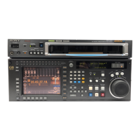
Highlights the core capabilities and technological advantages of the SRW-5000/SRW-5500 recorders.

Features of the Control Panel

Explains the different menu screens (HOME, TC, VIDEO, AUDIO, CUE, PF, SET UP) and their functions.

Chapter 3 Setting Up the VTR

3-1 Connecting External Equipment

Illustrates typical HD digital and NTSC/PAL connection configurations for playback and recording.

Making HD Digital Connections

Illustrates typical HD digital connection configurations for playback and recording.

Making NTSC/PAL Digital Connections

Shows how to connect for NTSC/PAL digital signals, including connecting to other VTRs.

Chapter 4 Menu Settings

4-1 Registering and Storing Menu Settings

Covers menu configuration, item registration, VTR memory banks, and memory stick operations.

Registering Items to the VTR SETUP Menu

Details the process of assigning frequently used items to function buttons.

VTR Memory Bank Function

Describes how to store up to eight sets of menu settings in VTR memory banks.

Memory Stick Operations

Covers formatting, saving, and recalling data to and from a memory stick.

Saving and Recalling DEFAULT Settings on a Bank

Explains how to save and recall factory default values for menu items.

Saving and Recalling DEFAULT Settings in a Memory Stick

Details saving and recalling default settings to and from a memory stick.

Record Inhibit Mode (REC INH)

Function to disable recording, with options for different areas.

Selecting the Edit Mode and Edit Channel

Covers selection between assemble and insert edit modes.

Setting the Time Data (TIMER SEL/RESET/SET/HOLD)

Allows selection, reset, setting, and holding of time data types.

Registering Cue Points

Instructions for setting cue points directly or via numeric input.

Selecting the Reference Signal (SERVO REF)

Choosing the signal source for VTR servo synchronization.

Adjusting the Output Video Signal (MASTER to FINE)

Adjusting various video parameters like levels, gain, phase, and black/setup levels.

Selecting the Audio Input Signal (AUDIO IN)

Configuring audio input sources for channels 1-12.

Digital Audio Output Signal Source Track Selection (DIGOUT EXCHNG)

Assigning audio tracks for digital output channels.

Analog Audio Output Signal Source Track Selection (ANAOUT EXCHNG)

Assigning audio tracks for analog output channels CH1-CH4.

Digital Audio Output Signal Source Track Selection (SDOUT EXCHNG)

Assigning audio tracks for SD SDI digital output.

VTR SETUP Menu

Accesses the comprehensive menu for VTR operating conditions and settings.

Chapter 5 Recording/Playback

5-1 Preparing for Recording

Outlines initial switch and menu settings required before starting recording.

Selecting Audio Signals

Details how to select audio input signals and channels for input and monitoring.

Adjusting the Recording Level

Procedure for setting and adjusting audio recording levels for each channel.

5-2 Recording

Provides step-by-step instructions for performing a recording operation.

Recording Procedure

Step-by-step instructions for performing a recording operation.

Adjusting the Audio Playback Level

Procedure for setting and adjusting audio playback levels for monitoring.

5-4 Playback

Covers various playback modes including normal, variable, and DMC.

Chapter 6 Editing

6-1 Basic Automatic Editing

Covers automatic editing modes, setting points, and basic editing procedures.

Overview of Automatic Editing

Introduces assemble and insert modes for automatic video editing.

Setting Edit Points

Instructions for setting IN and OUT points for video and audio.

Modifying Edit Points

Procedures for deleting or moving edit points by one frame unit.

Performing Automatic Editing

Steps to execute automatic editing once edit points are set.

Modifying Edit Points for Automatic Editing Later

How to adjust edit points after automatic editing has been performed.

6-2 Advanced Automatic Editing

Covers advanced editing techniques like DMC, animation, and preread editing.

DMC Editing

Performing variable speed editing using Dynamic Tracking.

6-3 Manual Editing

Provides a step-by-step guide for performing manual editing operations.

Manual Editing Procedure

Step-by-step guide for performing manual editing operations.

Appendix

Error Messages and Warning Messages

Lists and explains error messages, protection mode, and warning messages.

Error Messages

Describes messages indicating malfunctions or internal system errors.

Warning Messages

Lists and explains various warning messages that may appear during operation.

Related product manuals