HXR-NX5C/NX5E/NX5J/NX5M/NX5N/NX5P/NX5U
1-2
– ENGLISH –
Self-diagnosis Code
Symptom/State Correction
Repaired by:
Block
Function
Detailed
Code
E 6 2 1 1 Shift lens overheating (Pitch)
Inspect the IC6401 and peripheral circuits on the VC-582 board.
If it does not recover, replace the VC-582 board. (Note) If an
error occurs again, replace the lens block.
E 6 2 1 2 Shift lens overheating (Yaw)
Inspect the IC6401 and peripheral circuits on the VC-582 board.
If it does not recover, replace the VC-582 board. (Note) If an
error occurs again, replace the lens block.
E 6 2 2 0 Abnormality of lens thermister
Inspect the IC6401 and peripheral circuits on the VC-582 board.
If it does not recover, replace the VC-582 board. (Note) If an
error occurs again, replace the lens block.
E9 2 0 1
Battery current value goes over the max
discharge current
Check the remaining battery power because this symptom
maybe depended on the remaining battery level, and confirm
whether or not the symptom is occurred after replacing the
battery.
If the symptom is still occurred, overhaul inspection is
needed.
Connect the GC-012 board with VC-582 board through the
FP-1161 (VC-GC) flexible board.
Connect the GC-012 board with Control Switch Block
(PS94000).
Check each output of DC/DC converter (IC5201) on VC-582
board with connected the DC/Batt harness (the minimum con-
nection to periphery) to VC-582 board.
E9 4 0 0
Fault of writing or erasing the flash
memory
Inspect the flash memory (IC2601 on the VC-582 board).
E 9 4 0 1 Internal flash memory fault Inspect the flash memory (IC2601 on the VC-582 board).
E 9 4 0 2 BGM data error
Inspect the flash memory (IC2601 on the VC-582 board). If it
is OK, check the CPU (IC2001 on the VC-582 board).
E 9 5 0 0 GPS hardware error
Check whether the flexible board of the GPS module is bro-
ken, and check whether it is inserted imperfectly. If there is
no problem the flexible board, inspect or replacement of the
GPS module.
Note: When replacing the VC-582 board, remove the EEPROM (IC5602, IC5603) from the VC-582 board that is going to be repaired. Install the removed
EEPROM (IC5602, IC5603) to the replaced VC-582 board.
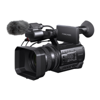
1-4. GPS RECEIVING CHECK(NX5E/NX5J/NX5N/NX5P/NX5U)
Set the GPS switch to ON.
appears, and your camcorder starts trying to triangulate. When your camcorder triangulates successfully, it will record the location
information at the time movies were recorded.
b
Notes
• The indicator changes according to the strength of GPS signal reception.
Triangulating status GPS indicators GPS reception status
Function off No indicator The GPS switch is set to OFF, or the GPS receiver is not
functioning normally.
Difficult
The camcorder cannot find a GPS signal, therefore, it can-
not triangulate. Use the camcorder in an open area.
Searching
The camcorder is searching the GPS signal. It may take
several minutes until the camcorder triangulates.
Triangulating The camcorder is receiving a weak GPS signal.
Triangulating The camcorder is receiving a GPS signal, and can acquire
location information.
Triangulating
The camcorder is receiving a strong GPS signal, and can
acquire location information.
• Even if a triangulating status indicator is displayed, the camcorder may not record the GPS information continuously, depending on the
condition of GPS signal reception.
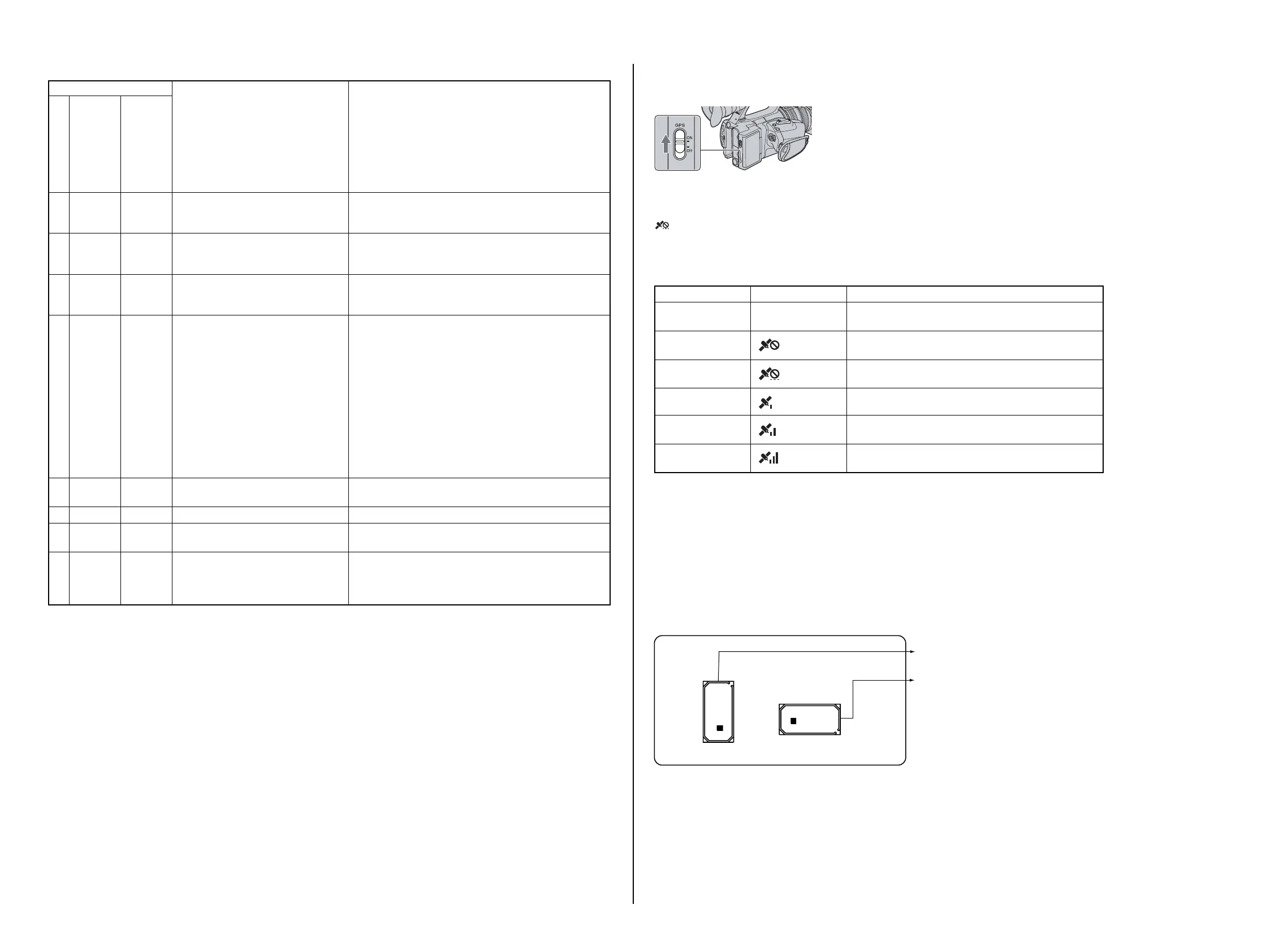
1-5. PRECAUTION ON REPLACING THE GY-022 BOARD
Angular Velocity Sensor
When you replace to the reparing board, write down the sensitivity displayed on the angular velocity sensor (SE8501, SE8502).
Start the Adjust Manual in the Adjust Station and execute the “GYRO sensor sensitivity adj”.
GY-022 BOARD (SIDE A)
SE8501
(PITCH SENSOR)
SE8502
(YAW SENSOR)
PP
YY
PP:
PITCH sensor sensitivity
t
G1
YY:
YAW sensor sensitivity
t
G2
Note: The sensor sensitivity of SE8501, SE8502 of GY-022 board is written only repair parts.
The changed portions from
Ver. 1.0 are shown in blue.
Ver. 1.1 2010.01
 Loading...