19
Rear
Panel
Service
Position
upside down
FU Board
Front
Panel
Floppy
Drive
Power Block
The power block consists of three sections with inter-functional opera-
tions:
Power Block Functions
Name Function
1. AC Power AC power only
2. Battery Power Battery power. Battery Charge
3. Battery Charge
Determination
Charge or not to charge
(Evaluation made when the battery is first
connected and again when the camera is
turned off). Needs AC power.
AC Power
The main power path for this camera is AC power from the DC In J902.
When this power plug is inserted several operations occur:
1. HI Control IC404 is powered
2. AC adapter input is detected
3. Battery Charge Determination signal is output
4. Battery is inhibited if connected
HI Control IC404 is powered
When the AC adapter is connected, 8.4V regulated DC is input to a bank
of fuses on the FU board. The voltage continues into the main FC-72
board for the power supply, Ever 3.2V regulator IC401 and out of the
board into the backlight power supply.
Voltage from F005 is used to power IC404. This voltage is applied through
D402 to Ever 3.2V regulator IC401. IC401 powers HI Control IC404.
AC adapter input is detected
Once IC404 is powered, it detects the presence of the AC power source
at pin 72.
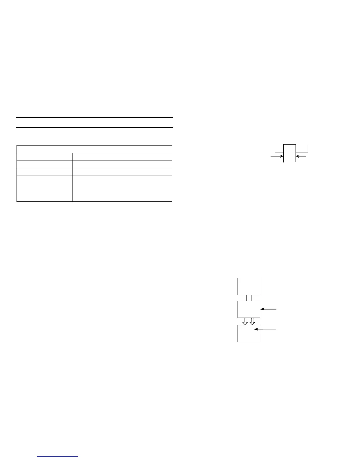
Battery Charge Determination signal is output
Once IC404 knows there is an AC power source, IC404 begins outputting
battery charge determining pulses at pin 27 even though there is no bat-
tery connected. The signal is a one second duration square wave that
starts at 0V and goes to 3.2V.
Battery is inhibited if connected
When the AC adapter plug is inserted into the camera, the battery is in-
hibited from powering the camera because it is assumed AC power is
available. The AC adapter plug has a broad negative contact that con-
nects the DC In J902/pin 3 to pin 2 (ground).
Grounding J902/pin 3 brings IC404/pin 20 Low so IC404 will not connect
the battery to the main camera circuit when the camera is ON. IC404
would normally connect the battery using pins 27 or 100 (not shown in this
diagram).
Service Position
The FU board is fully accessible while the camera is operational in the
PLAY mode.
1. Remove the rear panel.
2. Unplug the two lower left ribbon connectors from the main FC-72 board.
This disables the camera lens but frees the main board.
3. Lift the Floppy drive with main board up and fold the rear panel above
it so there are three panels. The FU board is in the front panel.

 Loading...


