31
Flash Operation
Before touching the Flash unit, you must discharge the large 300-
Volt Flash Capacitor. This is explained in the next section. The flash
unit and the interfacing FC-72 flash control boards are each replaced as
an assembly. The following questions and answers will quickly explain
what is required for the flash operation. The answers will allow you to
determine which board is causing the flash problem.
When will the flash go OFF?
The flash will go off if the following conditions are met:
• Mavica is in the Still picture taking (not Play or Movie) mode.
• Flash is enabled by the user (LCD does not have the symbol of a
lightning bolt circled with a diagonal line through it).
• Insufficient brightness from the CCD imager (camera section).
• Flash LED (middle of flash button) is lit meaning the flash capacitor is
charged.
• Shutter button is pressed.
How do I know the flash capacitor is charged?
When the flash is not disabled (active), HI Control IC404/pin 93 outputs a
HIGH (3.2Vdc as STB Charge) along CN301/pin 1 to the flash unit as-
sembly. This turns ON the charge oscillator within that charges its flash
capacitor. When the capacitor in the flash unit charges to the 300V thresh-
old, a pulse is output along CN301/pin 10 (XSTB Full) back to IC404 so
IC404 knows the flash unit is ready to fire. IC404 lights D701 inside the
flash button to tell the technician the capacitor is charged and to tell the
user the flash is ready/enabled. IC404 also lowers the STB Charge volt-
age to stop the oscillator.
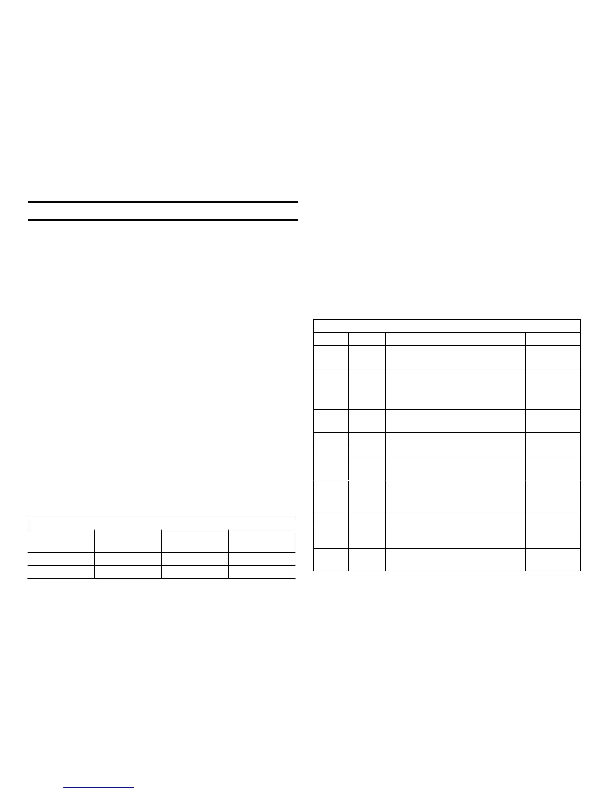
What commands are needed to fire the flash?
Flash Command
Name
FC-72 Bd
Location
Ready voltage Flash voltage
Shutter button CN002/pin 8 3.2Vdc 0Vdc
Strb ON CN301/pin 9 0Vdc + Pulse(s)
Flash Unit connector voltages ready to flash state
CN301 Signal Purpose Voltage
1
STB
Charge
Cap charge signal from FC board.
0V= stop charge, 3V = charge cap.
0V.
2 * STRB
Photo
On
HIGH from IC301 (FC-72 board)
during the flash cycle. Goes to 3V
when shutter is pressed. Returns
to 0V when cap is charged again.
0V
3 * Pop Up
On
Flash unit output pulse at the
conclusion of the flash.
0V
4 A 4.9V B+ to flash unit 5Vdc
5 Gnd Ground 0V
6 * Photo
Tr Out
Feedback voltage to control STRB
On pulse width (flash intensity).
0V
7 * Tally
LED
In the Self-Timer Mode, this LED
control goes LOW when the shutter
button triggers the timer to flash.
3.68Vdc.
(0V = timer
counting.)
8 Unreg Flash Capacitor Oscillator power 8Vdc
9STRB
On
+ Pulse fires flash. Pulse width
sets intensity
0V. + Pulse
fires flash
10 XSTB
Full
Low Pulse from flash unit to stop
STB charge signal (CN301/pin 1).
2.9Vdc
* Cannot inhibit the flash
How does the shutter button trigger the flash?
After the shutter button is pressed, the flash command is sent as data
through IC501 to IC301. Along with the flash command is a user decision
to force a flash or strobe the flash. IC301 monitors the light level from the
CCD imager signal and determines if a flash is required. IC301 outputs a
long duration single pulse to initiate a single full flash (normal) or short
duration pulses for strobe flashes preceding the full flash. These Strb On
flash pulse(s) from IC301 on the FC-72 board (CN301/pin 9) are used to
trigger the flash unit. The Strb On pulses can be observed with a scope.
What are the voltages at the flash unit connector?

 Loading...


