41
Floppy Disc Drive
The camera’s main FC-72 board contains the signal processing and mo-
tor control circuitry for the Floppy Drive Assembly. When the floppy drive
fails to play the disc, the problem can be the fuse, the floppy drive, or the
main board. The Floppy disc Drive is replaced as an assembly. The main
board is also replaced as an assembly.
The fastest way to determine if the drive, fuse (F001 on the FU board) or
main board is bad is to check the supply voltage. If the supply voltage is
good, substitute the floppy drive unit. If another drive unit is not available,
the last resort is to check for signals from the main board.
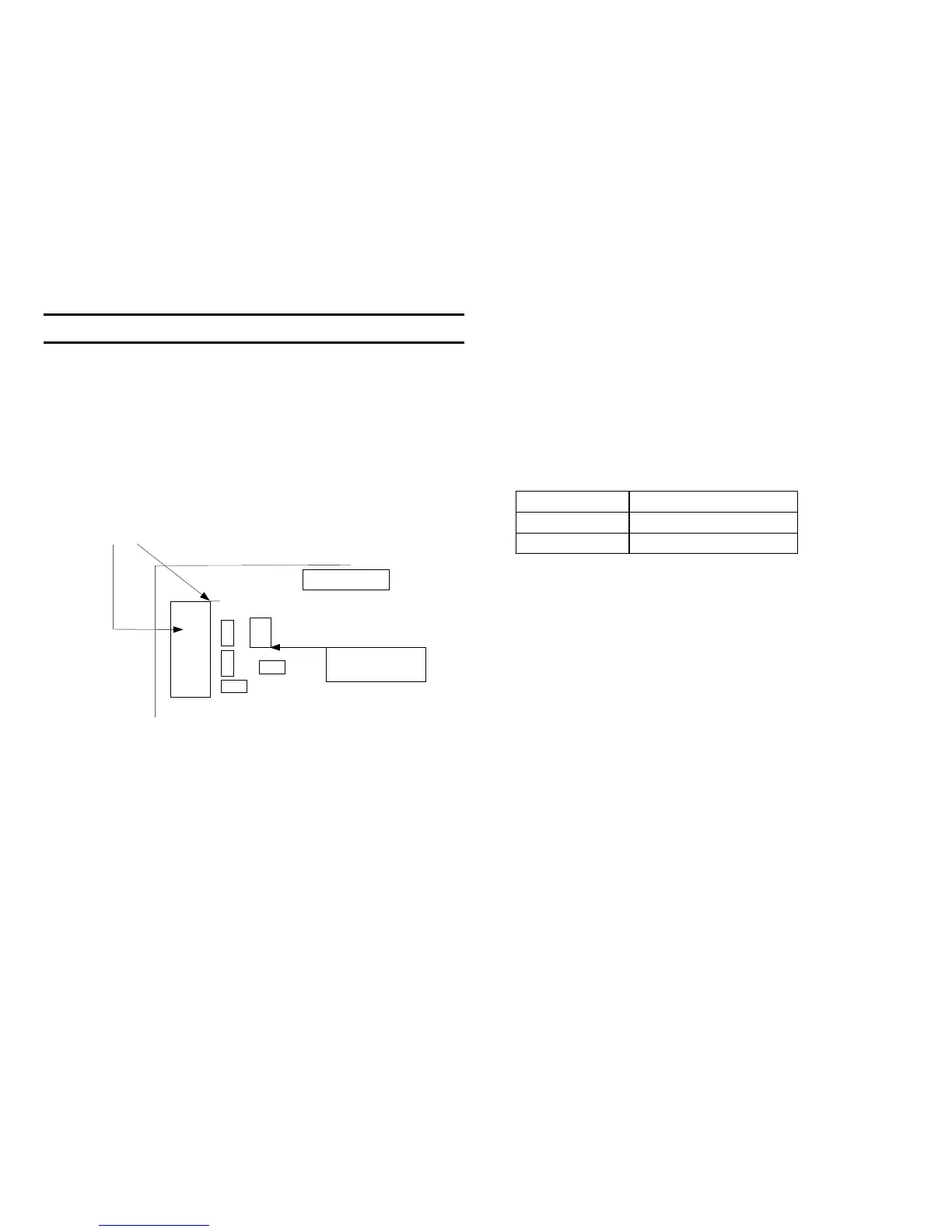
Checking for Floppy Disc Drive Voltage
FC-72 Board
CN701/pin 1
Testing for Drive
voltage on the
main FC-72
board
+5V from F001
to drive unit
Checking the Floppy Drive Signals
Some of the symptoms of a bad floppy drive are:
1. “Disc Error” or “File Error”
2. C:13:01 also disc error
3. After taking a picture, the picture is only partially displayed or half gray
(read/write heads break off - possibly from rapid disc insertion).
4 If the read/write heads are damaged they may still take pictures, but
after replacing the floppy drive, the old pictures may not open and are
lost. This is why you must test the drive’s alignment with both test discs.
Knowing how the floppy drive normally behaves and checking for motor
drive signals to the floppy drive is almost as good as substituting the
floppy drive unit itself. The input/output head signal is too low to be seen
on a scope so they cannot be used for testing.
Normal Operation
At power ON, HI Control IC404 (not shown) measures the voltage at the
drive’s disc in switch. 0V means the LCD panel will show “No Disk”. If
there is voltage present, a disc is in the drive and IC404 will begin reading
the disc in a process that begins when the spindle motor starts.
Voltage at CN701/pin 19
No Disc 0Vdc
Disc in drive 4.4Vdc
The following occurs when a disc is detected:
1. Disc In switch causes CN701/pin 19 to rise from 0V to 4.4V.
2. The Spindle motor is driven and the Disk Access lights.
3. The Stepper motor is driven so its heads are moved to the initial outer
track 00.
4. The Disc TOC is read and loaded into memory.
5. The stepper motor is moved inward to read the last picture data (Play
mode) or goes to an unused area of the disc (Still/Movie Mode).
6. After the data is read the:
• Spindle motor stops
• LED goes out
Spindle Motor Drive
The drive signals from the main FC-72 board to the spindle motor are at
CN701/pins 9-18. Since the spindle motor speed has to be controlled so
the data is not read too fast or too slow, clock pulses at CN701/pin 14 are
used to drive (increment) the spindle motor. The Index signal is a 5Hz
square wave from the floppy drive that is generated once for each revolu-
tion of the disc. This index pulse identifies a point on the disc that passes
the heads.

 Loading...


