49
Component Video Signal input to IC901
Name Location Voltage
Luminance (Y) IC901/pin 8 0.5Vp-p
R-Y IC901/pin 9 0.3Vp-p
Time Base = 20 usec/div.
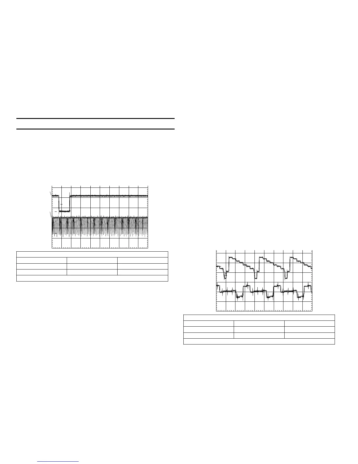
Sync input to PK Board
Name Location Voltage
Vertical sync IC904/pin 34 4.3Vp-p
Horizontal sync IC904/pin 37 4Vp-p
Time Base = 0.5 msec/div
LCD Block
The Liquid Crystal Display requires timing signals and the LCD drive.
Timing Signals
The timing signals identify each pixel of the display so the R, G or B
voltage level can be loaded into the display. All the timing signals are
made by Timing Generator IC904 using horizontal (HDO) and Vertical
(Panel V) signals input from IC301 (not shown) within the main FC-72
board.
CH1!2.00 V= PKD
CH2!2.00 V= MTB 500us- 1.84dv ch1+
1
2
T
Vert
sync
Horiz
sync
Timing generator IC904 is powered when the camera is turned ON, but
only after the LCD Driver IC901 receives power. To accomplish this, Q901
and Q902 serve as switches. The input is Panel 3.2V from the power
supply and the output is to IC904/pins 19 and 43. When Panel 13.2V
(also from the power supply) is present to power the LCD Driver, IC901,
Panel 13.2V is also used to turn ON the two transistor switches. The
switches bring the Panel 3.2V into IC904.
VCO
Timing Generator IC904 uses a high speed VCO to run. This VCO’s free
run frequency is at a multiple of the input horizontal sync and is adjusted
by setting the DC voltage from EVR IC902/pin 8. This procedure using
the service Remote Controller RM-95 is in the service manual. An off
frequency VCO produces a LCD picture consisting of just lines.
LCD Drive Signals
The signal from the camera or the floppy disc is processed by the main
FC-72 board and output as Luminance (Y), R-Y, and B-Y component video
signals. This signal is applied to LCD Driver IC901. LCD Driver IC901
has three functions:
• IC901 Converts the component video input to RGB output.
• IC901 Changes the color, contrast and brightness during the conver-
sion.
• IC901 Inverts every other line of the RGB output signal.
IC901 - Converts the component video input to RGB output
This is accomplished within IC901 using a transistor matrix that adds or
subtracts the input signal to produce the basic RGB output signal. For
example, the voltage R-Y is added to voltage Y to produce Red [(R-Y) + Y
= R].
By playing the TFD2 test floppy disc, the standard color bars can be se-
lected to produce these corresponding waveforms of Y and R-Y input
IC90.
CH1! 200mV~ PKD
CH2! 200mV~ MTB20.0us- 1.02dv ch1-
1
2
T
Y
R-Y

 Loading...


