vi
Battery Down Adjustment
These adjustments set both the camera’s shut off voltage and the LCD
battery indicator segment drop out points. The battery down adjustment
may change as the parts age, resulting in premature camera shutdown
when the battery is used. Therefore you should make this adjustment
after each repair.
Overview
The battery down adjustment is a multi-step process:
• Disable the shutdown circuit using the RM-95.
• Input the threshold voltage to the camera.
• Read that threshold voltage as a data level.
• Input that data level to the camera shutoff Address.
• Input relative data to set the LCD battery indicator segments.
• Enable the shutdown circuit.
Materials Needed
No disassembly is needed for this adjustment.
1. RM-95 Remote Commander P/N = J-6082-053-B
2. CPC-12 Adapter P/N = J-6082-436-A
3. Battery Simulator Power Cord P/N = J-6082-223-A
Checking the Battery Down Adjustment
Before performing the adjustment you can just check the setting with the
following procedure:
1. Connect the RM-95 Remote Commander to the camera with the CPC-
12 adapter.
2. Insert the Battery simulator into the camera and connect its wires to a
variable power supply set to 6Vdc.
3. Turn ON the camera and place the RM-95’s upper left corner slide
switch to “HOLD” (slide right).
5. Reduce the power supply voltage to 5.5Vdc and write down the RM-
95 data number. If the camera shuts down just as you reach 5.5Vdc
+01V, the adjustment is correct. If the camera shuts down before
5.5V, do the battery down adjustment starting at step 4.
6. Go to Page d, Address 90 and read the data. This data must be the
same as the number you copied down in the previous step. If it is not
the same you must perform the following battery down adjustment
starting at step 4.
Battery Down Adjustment Procedure
Disable the shutdown circuit
1. Connect the RM-95 Remote Commander to the camera with the CPC-
12 adapter.
2. Insert the Battery simulator into the camera and connect its wires to a
variable power supply set to 6Vdc.
3. Turn ON the camera and place the RM-95 upper left corner slide switch
to HOLD (slide right).
4. Disable Write Protect by going to Page 0, Address 01, and changing
the data from 00 to 01.
5. Disable the shutdown circuit by going to Page 6, Address 2c, and
changing the data from 00 to 01.
Shutdown Disable
Memory Location Change from / to Purpose
Page 0, Address 01 00 / 01 Write enable
Page 6, Address 2c 00 / 01 Shutdown disable
Measure the Input Voltage as Data
1. Set the RM-95 to memory location Page 2, Address 52.
2. Reduce the power supply voltage to 5.5Vdc +0.01V and write down
this RM-95 data reference number here: ______________.
4. Set the RM-95 to Page 2, Address 52.
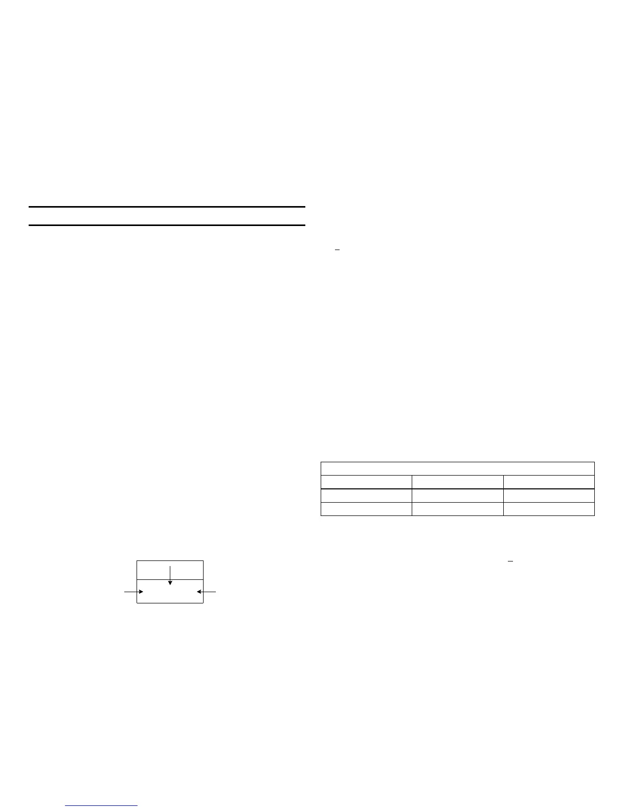
Data
Page Address
RM-95
Display
0 : 0 0 : 0 0

 Loading...


