SA-Z9R
11
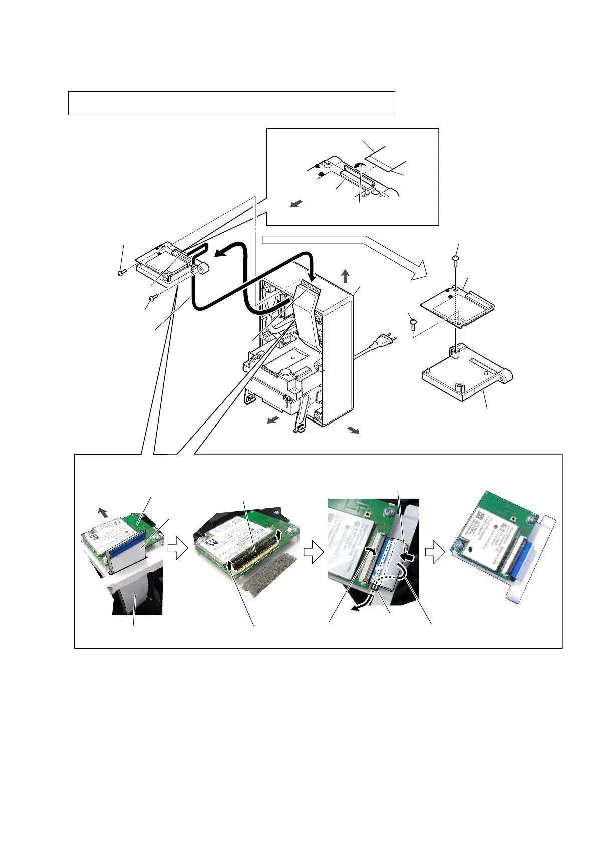
2-6. RF MODULATOR
front side
right side
cabinet block
hole
1 screw
(BVTP3 u 8)
2
1 screw
(BVTP3 u 8)
4
Draw out the FFC
block from the hole
of the stay block.
5 screw
(BVTP3 u 8)
5 screw
(BVTP3 u 8)
6 stay block
7 RF modulator
top side
FFC blcok
connector
3
Unlock the connector.
terminal
side
front side
terminal
side
+RZWRLQVWDOOWKH))&EORFN
front side
Attach in order from 1 to 5.
FFC block
RF modulator block
1
Pass the FFC block through the
hole of the RF modulator block.
connector
2
Lift up the lock plate
of the connector.
3
Insert the FFC block
to the connector.
4
Press down the lock plate
of the connector.
5
Pull out the FFC
block downward.
hole
Note: When the RF modulator is replaced, be sure to refer to “WIRELESS CONNECTION
(LINK) WORK OF BAR SPEAKER, SUBWOOFER AND REAR SPEAKERS” on page 4.
 Loading...