SA-Z9R
14
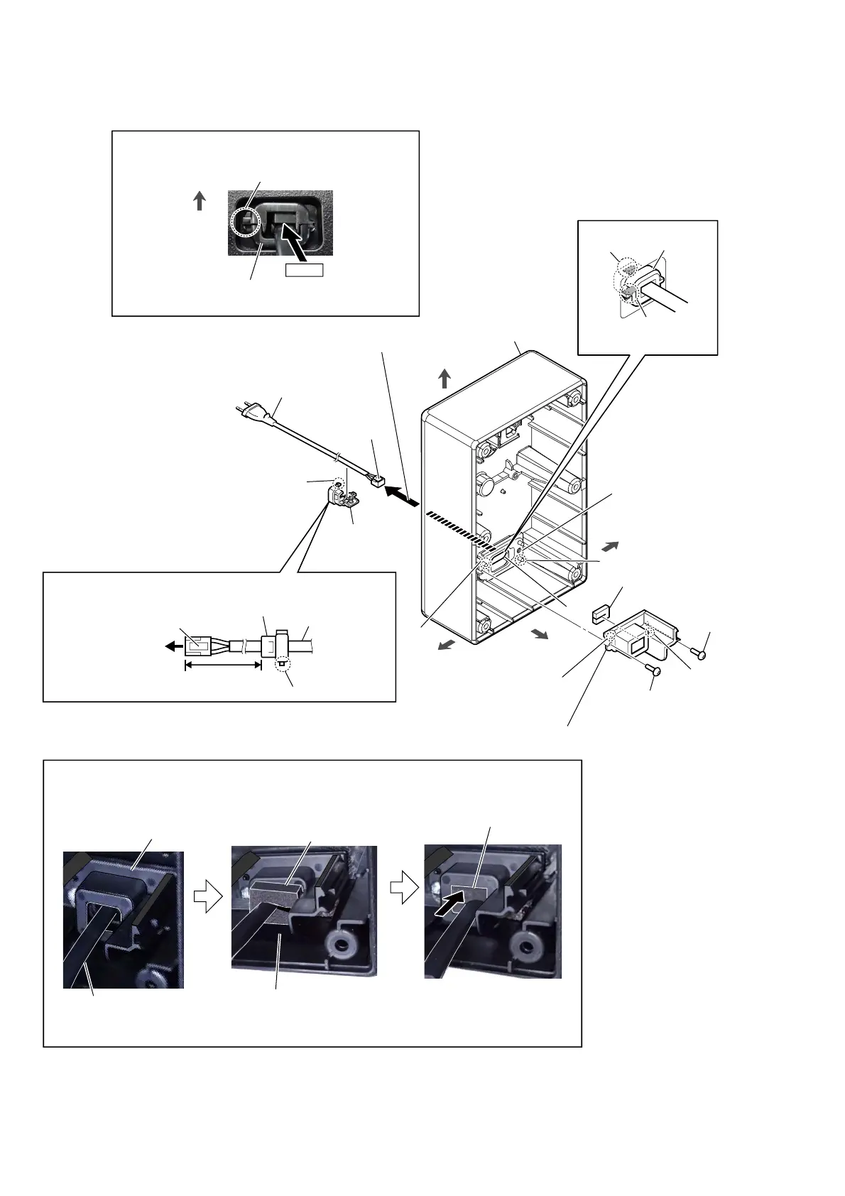
2-9. POWER-SUPPLY CORD
right side
top side
claw side
left side
8 power-supply
cord
power-supply cord
cord bushing (FBS001)
lock side
to switching regulator
5 Draw out the power-supply
cord block from the hole.
,QVWDOODWLRQSRVLWLRQRIWKHFRUGEXVKLQJ)%6
80
+5, -0 mm
7 cord bushing
(FBS001)
(See Fig. B)
6 Unlock.
claw side
cabinet block
front side
hole
packing (bushing)
1 screw
(BVTP3 u 8)
1 screw
(BVTP3 u 8)
2 bush case
Note:
When installing the bush case, align
the two bosses and two holes.
3 bushing (AC cable)
(See Fig. A)
boss
boss
hole
hole
+RZWRLQVWDOOWKHEXVKLQJ$&FDEOH
bushing (AC cable)
Attach in order from 1 to 2.
1
Pinch the
power-supply cord
block by the bushing (AC cable),
and insert the bushing (AC cable)
to the bush case.
2
Push the
bushing (AC cable),
to fit inside the bush case
as shown figure below.
bush case
power-supply cord block
)LJ$!
Push.
lock side
cord bushing (FBS001)
–,QQHUYLHZ–
top side
–5HDUYLHZ–
,QVWDOODWLRQGLUHFWLRQIRUWKHFRUGEXVKLQJ)%6
)LJ%!
cord bushing
(FBS001)
4 claw
4 claw
 Loading...