SA-Z9R
19
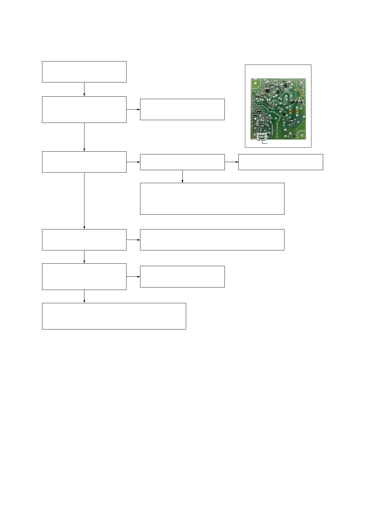
2. ON/STANDBY indicator does not light up (Power is not turned on)
– Switching regulator
(Conductor Side) –
ON/STANDBY indicator does not
light up.
(Power is not turned on)
The voltage of the following is about
21 V.
Switching regulator:
CN101 pin 1 to 3 (refer to Fig. A)
The voltage of the following is 4 V.
SK2 REAR MAIN board:
CN8022 pin 1 to 4
Yes
Switching regulator might have been
damaged. Replace the switching
regulator.
No
No
Check the pattern of area surrounding connector (CN8022) on
the SK2 REAR MAIN board and POWER4V line. If there is no
abnormality, replace the RF modulator.
The AC-CUT signal is inputted to
pin 28 of connector (CN8022) on
the SK2 REAR MAIN board after
AC input.
Check the mounted state of area
surrounding IC8016 on the SK2
REAR MAIN board, and repair it.
No
The voltage of the following is 4 V.
SK2 REAR MAIN board:
IC8015 pin 3
Yes
No No
Check the area surrounding connector (CN8022) on the SK2
REAR MAIN board. If there is no abnormality, the RF modulator
or SK2 REAR MAIN board are abnormality. Replace the RF
modulator or SK2 REAR MAIN board.
Resistor (R8299) on the SK2 REAR
MAIN board conduct the electricity.
Replace the resistor (R8299) on the
SK2 REAR MAIN board.
Check the mounted state of area surrounding IC8015 on the
SK2 REAR MAIN board do not short-circuits or opens. If there
is no abnormality, IC8015 on the SK2 REAR MAIN board might
have been damaged.
Replace the IC8015 on the SK2 REAR MAIN board.
Yes
Yes
Yes
– Fig. A –
CN101 pin 1 to 3
Yes
 Loading...