XAV-701BT/741
28
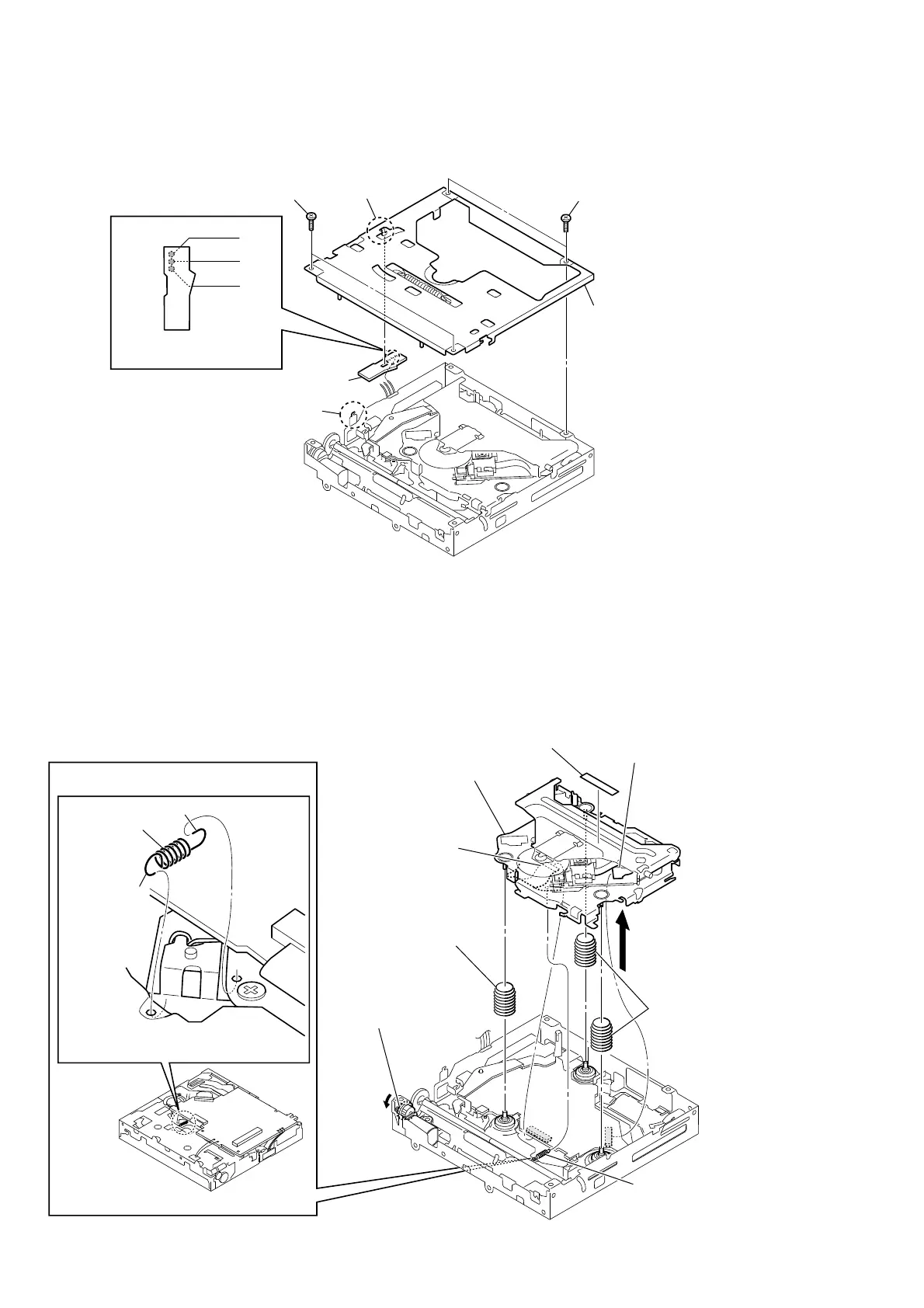
3-23. CHASSIS (T612Z) SUB ASSY, SENSOR BOARD
1
two precision
screws
(
P1.7
u
2.2
)
4
chassis (T612Z) sub assy
1
two precision
screws
(
P1.7
u
2.2
)
2
claw
3
claw
6
SENSOR borad
5
Remove the three solders
of SENSOR board wire.
RED
WHITE
BLACK
xxxxxxxxxxx
A
5
6
two
coil springs
(damper)
9
chassis (OP, ZA) complete assy
(OP1)
8
label (S)
7
compression
spring
(damper, Z)
2
sled motor
flexible
board
(
CN1
)
3
tension spring (KF)
tension spring (KF)
0HWKRGRILQVWDOOLQJWHQVLRQVSULQJ.)
4
Turn the gear (RA1) fully
in the direction of arrow A.
Hang in order of A, B by pay
attention spring of direction.
A
B
±%RWWRPYLHZ±
1
OP flexible board
(
CN2
)
Note:
When disconnecting the OP flexible board
from of the connector. Be sure to refer to
“NOTE FOR FLEXIBLE BOARD OF THE
OPTICAL PICK-UP” of the servicing notes
(See page 6).
3-24. CHASSIS (OP, ZA) COMPLETE ASSY (OP1)
 Loading...