 Loading...
Do you have a question about the Sony XAV-701BT and is the answer not in the manual?
| Brand | Sony |
|---|---|
| Model | XAV-701BT |
| Category | Car Stereo System |
| Language | English |
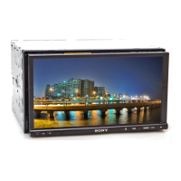
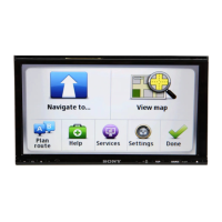
Details of the Wide LCD color monitor specifications, including dimensions and pixel count.
FM and AM tuning ranges, intermediate frequencies, sensitivity, selectivity, and frequency response.
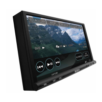
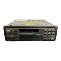
Specifications for the DVD/CD player, including signal-to-noise ratio and distortion.
Outlines Bluetooth version, power class, range, and frequency band for wireless connectivity.
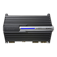
Specifies speaker outputs, impedance, and maximum power output of the amplifier.
Precautions for preventing electrostatic breakdown and handling delicate flexible boards of the optical pick-up.
Explains characteristics of unleaded solder and precautions for its use in repairs.
Warns about data loss on the XAV-701BT during repairs like display board replacement or initialization.
Advises that IC4 and IC11 on the SERVO board cannot be exchanged individually and require board replacement.
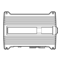
Provides a diagram showing the location of the model identification label on the bottom view of the unit.
Provides a step-by-step flow chart for disassembling the unit, indicating page numbers for each step.
Details the procedure for disassembling the front panel block, including notes on power and flexible cable installation.
Explains how to remove the display board, including desoldering, bending claws, and handling heat transfer sheets.
Details the removal of the DVD mechanism deck, including flexible flat cable installation notes.
Provides steps for removing the SERVO board, including desoldering wires and disconnecting flexible boards.
Details the procedure for executing the "Flicker Adjustment" after replacing monitor or display components.
Step-by-step guide for performing flicker adjustment using communication software and a remote commander, explaining input commands and value changes.
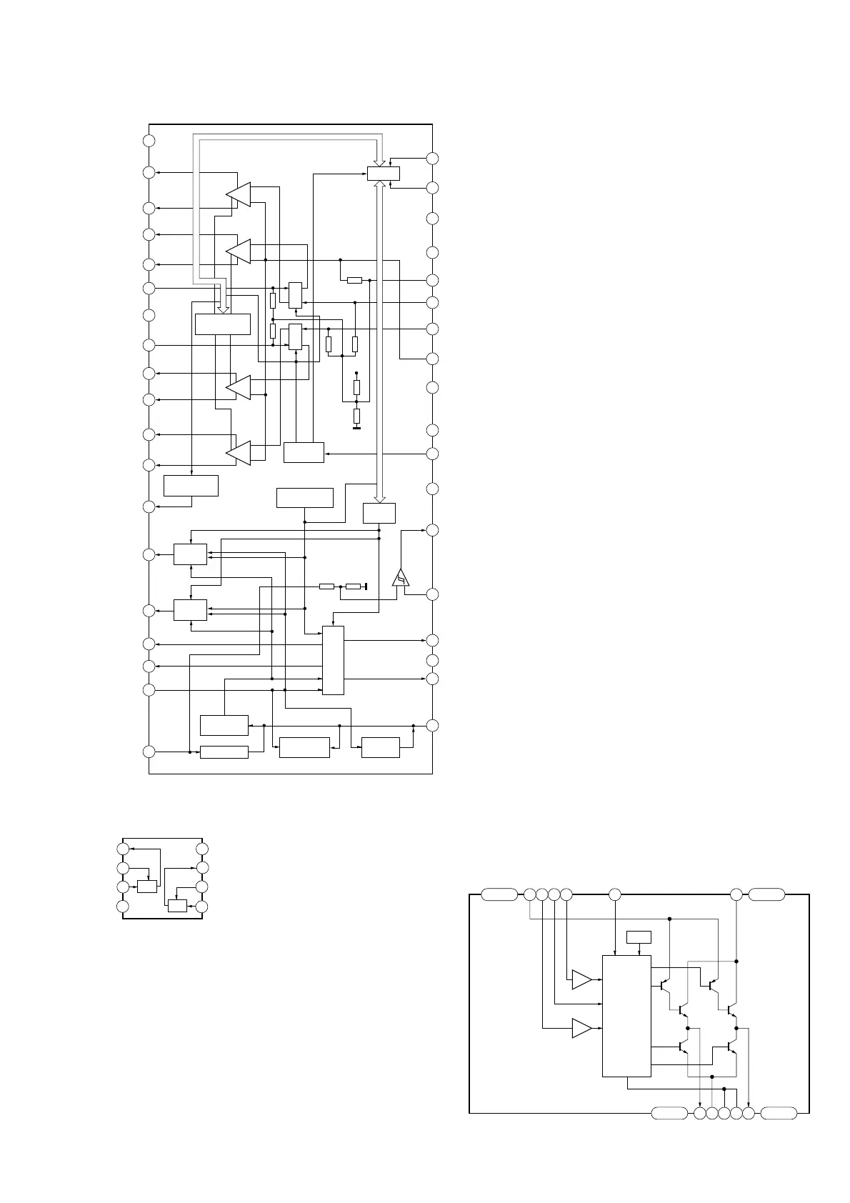
Shows the overall block diagram of the SERVO section, illustrating signal paths and major components.
Provides the printed wiring board layout for the SERVO section, identifying component placement.
Presents the first part of the SERVO section schematic diagram, detailing circuit connections and component values.
Shows the component side layout of the MAIN board's printed wiring, highlighting major ICs and connectors.
Presents the first part of the MAIN board schematic, detailing power supply and control circuits.
An exploded view of the entire unit, showing the main assembly and parts with their reference numbers.
An exploded view of the front panel assembly, detailing components like the display, touch panel, and base panel.
An exploded view of the KEY7 board assembly, showing buttons, filters, and covers with their respective part numbers.
An exploded view showing the MAIN board, including its connections to the FM/AM tuner unit and DC fan.
An exploded view of the DVD mechanism deck, showing chassis, springs, dampers, servo board, and screws.
Lists electrical components for the EXT-NAVI board, including capacitors, connectors, ICs, transistors, resistors, and flexible cables.
Lists part numbers for the complete MAIN board for the XAV-701BT (SAF) model.
Lists electrical components for the SERVO board, including switches, capacitors, connectors, ICs, transistors, and resistors.