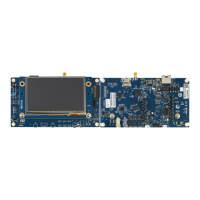
7 Board functions
7.1 TFT color LCD 480x272 pixels
The STM32H735G-DK board includes a 4.3-inch 480x272 LCD-TFT board (MB1315), which is connected to the
RGB interface of the STM32H735IGK6U through a 50-pin connector (CN19). The MB1315 LCD board uses the
RK043FN48H-CT672B TFT-LCD from Rocktech with the driving system, white LED backlight, and capacitive
touch panel. The touchscreen controller interfaces with the STM32H735IGK6U via the bidirectional I2C4 bus,
since the TFT LCD reset is controlled by PH6 GPIO (LCD_RST signal) by default (SB43 ON and SB44 OFF). The
possibility to control the LCD reset by the general reset (NRST) is also available on the STM32H735G-DK board.
In this case, SB44 must be ON and SB43 OFF.
7.2 USB OTG FS
The STM32H735G-DK board supports USB OTG full-speed communications via the CN14 USB Micro-AB
connector. The USB connector can power the STM32H735G-DK board with a 5V DC supply voltage, at a current
up to 500 mA. A USB power switch is also connected to V
BUS
and provides power to CN14. The green LED LD4
is lit when one of the following events occurs:
• The power switch is ON and STM32H735G-DK operates as a USB host.
• V
BUS
is powered by another USB host when the STM32H735G-DK board works as a USB device.
The red LED LD7 is lit when an overcurrent occurs (Current higher than 500 mA).
Note: The STM32H735G-DK board must be powered by an external power supply when using the OTG function.
7.3 Ethernet
The STM32H735G-DK board supports 10/100-Mbit Ethernet communication with a MICROCHIP LAN8742A-CZ-
TR PHY and integrates an RJ45 connector CN3. The Ethernet PHY is connected to the STM32H735IGK6U
microcontroller via an RMII interface.
The PHY 25 MHz clock is generated from the X1 oscillator, while the PHY RMII_REF_CLK generates the 50 MHz
clock for the STM32H735IGK6U.
7.4
Power over Ethernet
The STM32H735G-DK board integrates a power module that uses Ethernet. This module is an IEEE802.3af
compliant, class 1 / 2 PoE converter based on the simple diode rectified Flyback topology around the PM88800A
component from ST. This module “Powered Device” accepts an input voltage of 48 V and is able to provide 5 V
with 600 mA.
7.5 microSD™ card
A slot (CN2) for microSD
™
card (SD 2.0 compliant) is available on the STM32H735G-DK board and is connected
to the SDOI1 interface of the STM32H735IGK6U. The microSD
™
card detection is managed by the uSD_Detect
signal (PF5). When a microSD
™
card is inserted in the slot, the uSD_Detect signal level is LOW, otherwise, it is
HIGH.
7.6 Audio
An audio codec WM8994ECS/R from CIRRUS with four DACs and two ADCs is connected to the
STM32H735IGK6U SAI1 interface.
It communicates with the STM32H735IGK6U microcontrollers via an I²C-bus shared with the touch panel of the
RGB LCD and the STMod+ connector. The I²C-bus address of the WM8994ECS/R coded is 0011010.
UM2679
Board functions
UM2679 - Rev 1
page 16/42

 Loading...


