Limitations:
On the STM32H735G-DK board, SPI5 and UART7 signals are sharing the same IOs with SAI1. As a
consequence, when using SPI5 or UART7 signals to control a device connected to STMod+, the audio codec
cannot be used. Same, the user must make sure that nothing is connected on Pmod
™
(1,2,3,4 pins) and
ARDUINO
®
(D10, D11, D12, D13 pins) connectors.
8.5
P1 Pmod
™
connector
The standard 12-pin Pmod
™
connector is available on the STM32H735G-DK Discovery board to support low
frequency, low I/O pin count peripheral modules. The Pmod
™
interface which is implemented on
STM32H735IGK6U Discovery board is compatible with the Pmod
™
type 2A and 4A I/O signal assignment
convention.
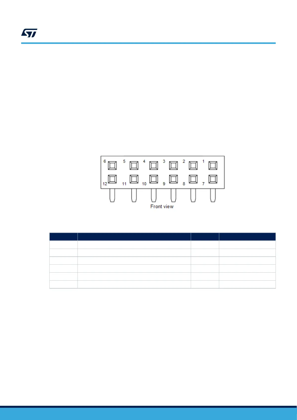
Figure 14. P1 Pmod
™
connector
Table 16. P1 Pmod
™
connector pinout
Pin number Description Pin number Description
1 SPI5_NSS / USART7_CTS (PF6/PF9) 7 INT (PH12)
2 SPI5_MOSI / USART7_TX (PF9/PF7) 8 RESET (PH1)
3 SPI5_MISO / USART7_RX (PF8/PF6) 9 NA
4 SPI5_SCK / USART7_RTS (PF7/PF8) 10 NA
5 GND 11 GND
6 3V3 12 3V3
Limitations:
On the STM32H735G-DK board, SPI5 and UART7 signals are sharing the same IOs with SAI1. As a
consequence, when using SPI5 or UART7 signals to control a device connected to Pmod
™
, the audio codec
cannot be used. Same, the user must make sure that nothing is connected on STMod+ (1,2,3,4 pins) and
ARDUINO
®
(D10, D11, D12, D13 pins) connectors.
UM2679
P1 Pmod™ connector
UM2679 - Rev 1
page 23/42

 Loading...


